Hardware Overview and Setup#
This chapter will give you basic hardware information about the MFN 100 and show you how to install and set it up.
The MFN 100 is a qualified Nerve Device that is optimized and tested for use with Nerve software. The device is designed for use in harsh industrial environments.
Contents#
The MFN 100 is shipped with a User an Installation Guide and a mating connector.
| Hardware | Software |
|---|---|
|
Pre-configured
|
Note
You will also need to download the CODESYS Development System. Please visit store.codesys.com to do so.
Identifying the MFN 100#
The label of the MFN 100 can be found on the back of the device, close to the DIN rail clip. Exact identification is possible through the combination of product number (P/N), serial number (S/N) and version number (V/N) that are printed on the label. The model number of the MFN 100 details the variant of the MFN 100 you have purchased:

| Letter or Number | Description |
|---|---|
| CODESYS indicator | This letter indicates whether the device has a CODESYS runtime pre-configured:
|
| SSD size | This number indicates the size of the SSD:
|
| CPU variant | This indicates the CPU variant of the device:
|
Note
Please make sure to write down the serial number of your Nerve Device. You are going to need it for the node registration process.
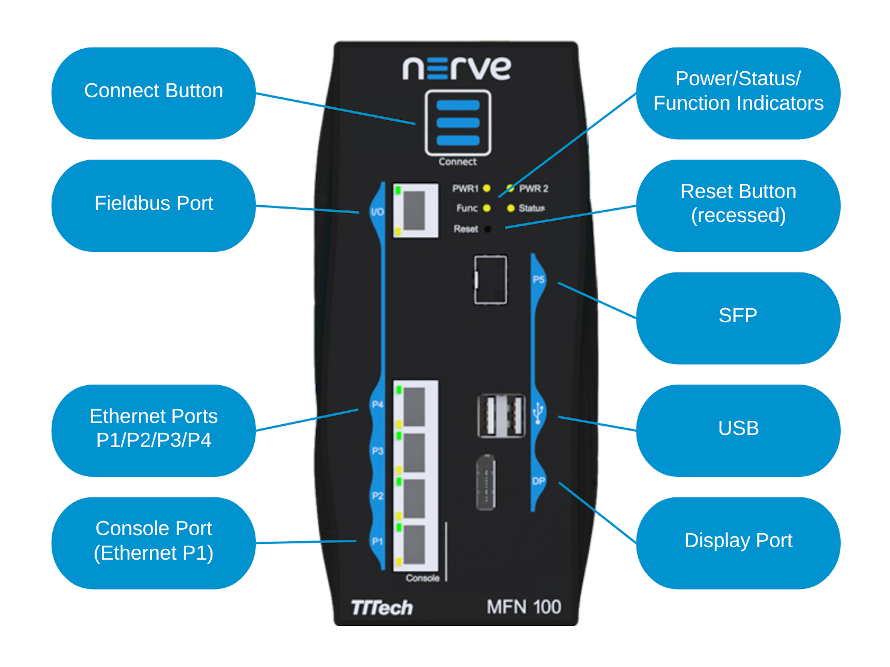
Front Panel Controls and Indicators#
Below is an overview of the front panel of the MFN 100, describing physical interfaces, indicators and their labels.
| Label | Description |
|---|---|
| Connect Button | The connect button interrupts the connection on ports P2 to P5 of the MFN 100. This is the behavior in the standard configuration. The function is configurable on request. The button may be configured to change the network configuration. |
| Connection Indicator | The connection indicator is the first fin in the MFN 100 housing. It lights up blue when all required services are initiated and the connection to the Management System is configured. |
| Reset | Holding the button for 4-8 seconds initiates a power cycle. Use a tool with a rounded tip to press the button. |
| Power 1 Power 2 |
Indicators showing power active on the power supply inputs. |
| Status | LED indicating system status
|
| Function | LED indicating CODESYS runtime status
|
| P1 Console | Ethernet port/console port. This port is typically used to connect a workstation to configure the MFN 100. |
| P2/P3/P4 | Ethernet ports |
| P5 | SFP port |
| I/O | Fieldbus interface |
| USB | Two USB 2.0 ports with 1.1 A maximum output current for both ports combined. |
| DP | Display Port supporting the DP++ standard. |
Power Connectors Overview#
The power connectors are located at the bottom of the MFN 100 next to the label. There are two separate 24 V inputs, two GND inputs and one Functional Earth (FE) input. The inputs are fused internally. The fuse cannot be replaced by the user. The power supply inputs are protected against reverse polarity.

| Pin | Description |
|---|---|
| 1 | Functional Earth (FE) |
| 2 | Power supply line 1 |
| 3 | GND |
| 4 | GND |
| 5 | Power supply line 2 |
Note
The GND and FE pins (pins 2, 3, and 5) are electrically connected to the housing.
Power Supply Details#
| Parameter | Value |
|---|---|
| Operating voltage | 18 - 30 VDC |
| Start-up current | 7 A max. |
| Consumption | 1.4 A continuous 2.1 A peak |
| Dissipated power | 33.6 W at 24 VDC |
Installation and Removal on a DIN Rail#
The MFN 100 is intended for mounting on a DIN rail inside a closed cabinet. Due to its weight it should be installed on a strong DIN rail. No tool is required to install or remove the MFN 100.
Follow these steps to install the MFN 100 on a DIN rail:
- Engage the DIN rail mounting clip of the MFN 100 with the upper edge of the DIN rail.
- Push the MFN 100 down into the DIN rail.
- Place the MFN 100 in a vertical position so that the mounting clip engages the lower edge of the DIN rail.
If you want to remove the MFN 100 from a DIN rail, follow these steps:
- Push the MFN 100 down.
- Rotate the MFN 100 upwards so that the lower edge of the DIN rail disengages.
- Lift the MFN 100 slightly to remove it.
Setting up the MFN 100#
You will need two network cables and a +24 V DC power supply for the setup. After mounting the MFN 100 on a DIN rail:
- Connect pin 1 of the mating connector to +24 V DC.
- Connect pin 2 of the mating connector to GND.
- Plug the mating connector into the bottom side of the MFN 100.
-
Connect port 2 of the MFN 100 to a DHCP-enabled network with access to the Management System or internet access if the Management System is hosted by TTTech Industrial.
Note
If you are not sure how to allow external devices to connect to your network, please contact your IT administrator.
-
Plug in the power supply.
The MFN 100 will start after a few minutes and light up blue when all necessary services are initiated.
Note
- If you want to connect the MFN 100 to a fieldbus, connect a network cable to the I/O port of the MFN 100 and to your fieldbus interface.
- You can also connect a second power supply to the MFN 100 as a backup. To do so, connect pin 3 of the mating connector to GND and connect pin 4 of the mating connector to +24 V DC.