Node Internal Networking#
This chapter explains how a user can connect workloads (VMs and Docker containers) to services and network ports of a node. In order to do this, it explains the internal networking concepts in detail. Most workloads will need to be connected to a network as networking is the main form of communication for workloads. They either want to connect to external servers or they are servers themselves, in which case they need to be made visible for their communication partners. The Nerve networking system enables both use cases.
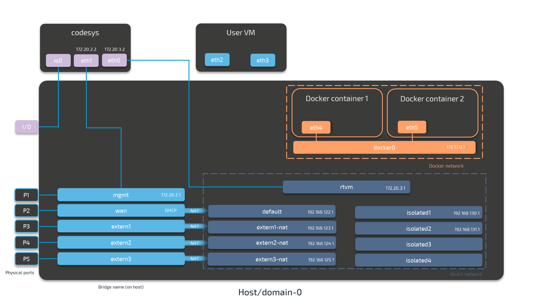
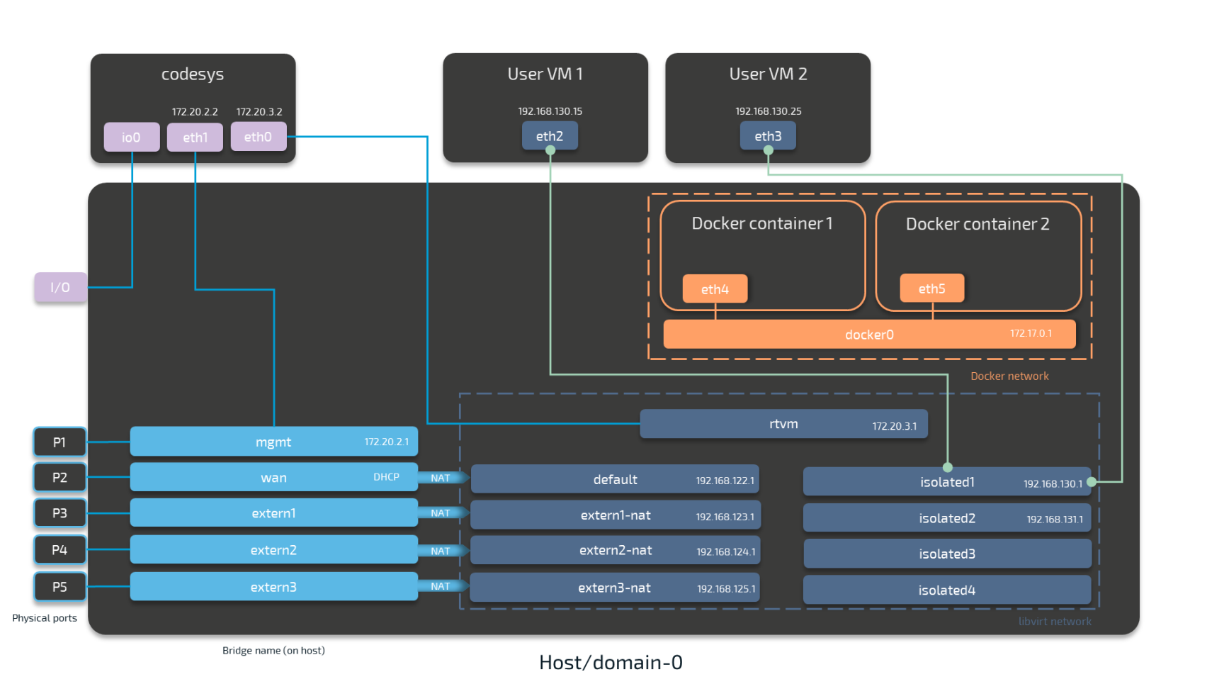
The image below shows an example node consisting of the host/domain-0 and the real-time VM running the CODESYS runtime (labeled codesys). To further clarify the networking example it also has one Virtual Machine workload and two Docker workloads deployed. The virtual machine is located outside of the host and the Docker containers are located in the Docker network inside of the host. For the sake of the example, however, the workloads are not yet connected. This is done in the examples further below.
The physical ports P1 to P5 and I/O of the Nerve Device (the MFN 100 in this case) are displayed on the left, touching the host. The black interfaces connected to them inside the host are Linux bridged interfaces displayed with their names on the host. Highlighted by a purple dashed frame is the libvirt network with NAT interfaced being on the left and isolated interfaces on the right. Slightly above them is the rtvm interface. Highlighted by an orange dashed frame is the Docker network including the Docker gateway (the orange interface labeled docker0). All interfaces colored in red are related to the CODESYS runtime. Interfaces labeled eth are symbolic representations of interfaces that are used by virtual machines and Docker containers for communication with the Nerve Blue system. The actual interfaces used depend on the Docker container or virtual machine.
Connections are displayed in three ways. Blue lines are connections that are predefined by the system. Blue arrows are used between bridged interfaces and the libvirt network to indicate NAT. Orange lines indicate the connection between Docker containers and the Docker gateway inside the default Docker network. Further down below, green lines are used as example connections that can be done by the user.
As mentioned above, the image below represents the MFN 100. Please see the device guide for information on your Nerve Device as the physical ports and the connection to their respective interfaces differ.
Note
codesys refers to the name of the CODESYS runtime in the Nerve Blue system. When the CODESYS Development System is referenced, CODESYS is always written in capital letters.
Please see the table below for more information on the interfaces, their usage and their IP ranges.
| Legend | |
|---|---|
| Physical Ports | These ports are device dependent. They are included here for clarification of the image above. Please see the device guide for information on your Nerve Device.
|
| Bridged Interfaces |
|
| NAT Interfaces | IP addresses are assigned by a DHCP server when NAT interfaces are used. The IP address is assigned in subnet 255.255.255.0.
|
| Isolated Interfaces | Isolated interfaces can be used to allow communication between two virtual machines. These networks cannot communicate outside of the system.
|
| Other interfaces | Other interfaces that can be used as a NAT network but without port forwarding. These interfaces do not communicate outside of the system.
|
| Connections |
|
The following sections are conceptual explanations. Workloads are attached to internal networks during the provisioning process. Please refer to the provisioning chapters (Virtual Machine workloads and Docker workloads) in the user guide on how to provision workloads.
Attaching Virtual Machines to a Network#
Virtual machine networking is comparable to installing a network card in the virtual machine and attaching it to the network with the network name given in the network drawing. For this example, there are two "network cards" installed in a user deployed virtual machine. They are labeled eth2 and eth3 in this example. Green lines indicate a user established connection.

There are two connections established here: eth2 is connected to the mgmt bridged interface for communication with the CODESYS runtime inside of the system. eth3 is connected to the default NAT interface for an internet connection protected by NAT on P2 of the Nerve Device. Both interfaces have IP addresses in the designated ranges. 172.20.2.15 for eth2 was manually configured in the virtual machine and 192.168.122.16 for eth3 was assigned by the DHCP server.
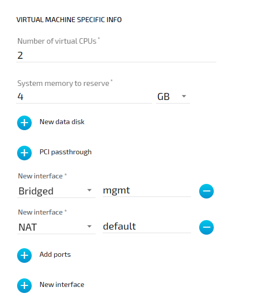
Settings Example#
To achieve the functionality above, configure the interfaces of the Virtual Machine workload the following way during the provisioning process in the Management System:
Communication of a Virtual Machine with a Docker Container and the CODESYS Runtime#
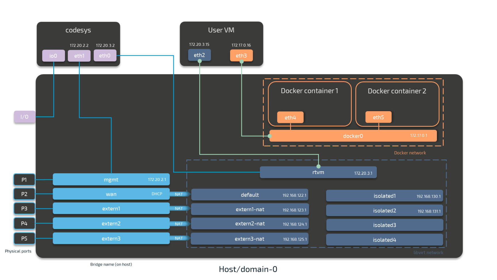
For Docker containers the situation is different. Docker containers are automatically attached to the Docker default network and access other parts of the system through this network. It is typically called docker0 and has the IP address 172.17.0.1 assigned. In order to make a server accessible for other workloads, you need to map the port and protocol of the Docker container to the outside by specifying this during workload provisioning in the port mapping section.
A virtual machine can communicate with Docker containers by connecting an interface to the Docker gateway docker0. In the example below this is done with interface eth3 that has the IP address 172.17.0.16 in the default Docker network. The IP address was manually configured.
Workloads can also be attached to the CODESYS runtime through Nerve networking. For this, the "network card" of the virtual machine is attached to the rtvm network.
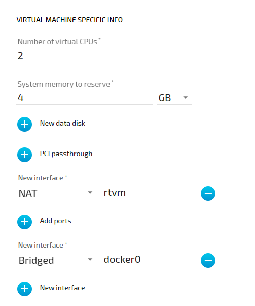
Settings Example#
To achieve the functionality above, configure the interfaces of the Virtual Machine workload the following way during the provisioning process in the Management System:
Communication of Two Virtual Machines through Isolated Networks#
Nerve Blue offers isolated network interfaces for communication of workloads inside of the system. These interfaces do not communicate outside of the system. They can be used to establish communication between two Virtual Machines.
Both virtual machines have a "network card" installed. User VM 1 is connected to the isolated1 interface through eth2 and User VM 2 is connected through its interface eth3 to the same network interface, isolated1. Each interface has been assigned an IP address by a DHCP server in the designated range: 192.168.130.15 for eth2 and 192.168.130.25 for eth3.
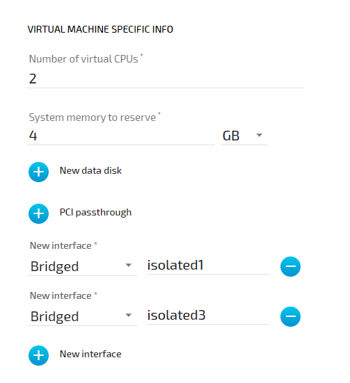
Settings Example#
To achieve the functionality above, configure the interfaces of the Virtual Machine workload the following way during the provisioning process in the Management System:
List of Reserved TCP/UDP Ports#
The following list states ports that are reserved in version 2.0.
| Port | Interface | Protocol | Reserved for |
|---|---|---|---|
| 22 | none | TCP | SSH daemon |
| 514 | 127.0.0.1 | TCP/UDP | System Log |
| 1883 | 127.0.0.1 | TCP | Local MQTT broker |
| 1884 | 127.0.0.1 | TCP | Local MQTT broker |
| 3000 | 172.20.2.1 | TCP | Local UI |
| 9000 | 127.0.0.1 | UDP | Filebeat |