Sending data to MS Azure IoT Hub
This example demonstrates the basic usage of the Gateway's Azure IoT Hub device output in order to show how to provide a bridge between Nerve Blue and Microsoft's IoT infrastructure. The instructions below describe an easy-to-use way to send data from an MQTT demo sensor to an MS Azure IoT Hub device.
Note
An MS Azure IoT Hub device is required before attempting the following example. Refer to the official Microsoft Azure IoT Hub documentation in the section Create a hub using the Azure portal for more information.
Provisioning and deploying the sensor simulation and the MQTT broker
In the instructions below two Docker workloads will be provisioned and deployed:
An MQTT broker must to be deployed to the node first in order for the sensor simulation to function. The EMQX MQTT broker is used in this example that can be downloaded from the Docker Hub registry.
Afterwards the temperature and humidity sensors simulation MQTT publisher is deployed. Download the Data Services MQTT demo sensor found under Example Applications from the Nerve Software Center. This is the Docker image that is required for provisioning the demo sensor as a Docker workload.
- Log in to the Management System. Make sure that the user has the permissions to access the Data Services.
-
Provision a Docker workload for the EMQX MQTT broker by following Provisioning a Docker workload. This example uses emqx-4.1.0 as the workload name. Use the following workload version settings:
Setting Value Name Enter any name for the workload version. Release name Enter any release name. DOCKER IMAGE Select From registry and enter emqx/emqx:v4.1.0.Container name emqxNetwork name host -
Provision a Docker workload for the sensor simulation by following Provisioning a Docker workload. Use the following workload version settings:
Setting Value Name Enter any name for the workload version. Release name Enter any release name. DOCKER IMAGE Select Upload to add the Docker image of the sensor simulation that has been downloaded before. New environment variable Select the + icon and enter the following information: - Env. variable
MQTT_PUB_TOPIC - Variable value
demo-sensor-topic
Container name ttt-mqtt-demo-sensor-1.0Network name host - Env. variable
-
Deploy both provisioned Docker workloads above by following Deploying a workload.
Configuring the Data Services Gateway on the node
With the MQTT broker and demo sensor deployed, the Gateway configuration is next. For the sake of simplicity and ease of use, the example configuration below omits any parameters that are not required.
-
Access the Local UI on the node. This is Nerve Device specific. Refer to the table below for device specific links to the Local UI. The initial login credentials to the Local UI can be found in the customer profile.
Nerve Device Physical port Local UI MFN 100 P1 http://172.20.2.1:3333 Kontron KBox A-150-APL LAN 1 <wanip>:3333
To figure out the IP address of the WAN interface, refer to Finding out the IP address of the device in the Kontron KBox A-150-APL chapter of the device guide.Kontron KBox A-250 ETH 2 <wanip>:3333
To figure out the IP address of the WAN interface, refer to Finding out the IP address of the device in the Kontron KBox A-250 chapter of the device guide.Maxtang AXWL10 LAN1 <wanip>:3333
To figure out the IP address of the WAN interface, refer to Finding out the IP address of the device in the Maxtang AXWL10 chapter of the device guide.Siemens SIMATIC IPC127E X1 P1 http://172.20.2.1:3333 Siemens SIMATIC IPC427E X1 P1 http://172.20.2.1:3333 Supermicro SuperServer E100-9AP-IA LAN1 <wanip>:3333
To figure out the IP address of the WAN interface, refer to Finding out the IP address of the device in the Supermicro SuperServer E100-9AP-IA chapter of the device guide.Supermicro SuperServer 1019D-16C-FHN13TP LAN3 http://172.20.2.1:3333 Supermicro SuperServer 5029C-T LAN1 <wanip>:3333
To figure out the IP address of the WAN interface, refer to Finding out the IP address of the device in the Supermicro SuperServer 5029C-T chapter of the device guide.Vecow SPC-5600-i5-8500 LAN 1 http://172.20.2.1:3333 Winmate EACIL20 LAN1 <wanip>:3333
To figure out the IP address of the WAN interface, refer to Finding out the IP address of the device in the Winmate EACIL20 chapter of the device guide. -
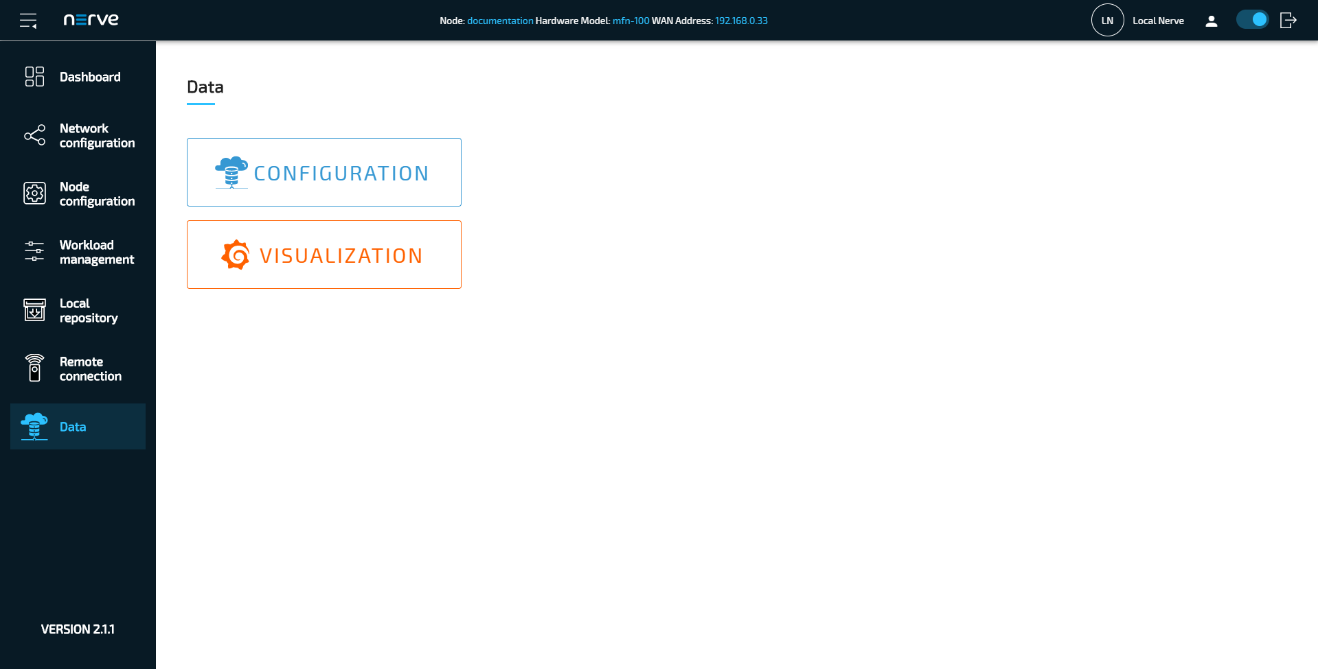
Select Data in the navigation on the left.
-
Select CONFIGURATION.
-
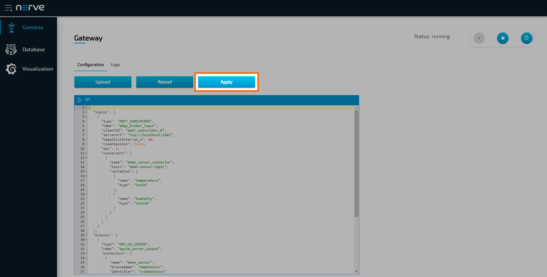
Enter the following configuration into the configuration editor of the Gateway:
{
    "inputs": [
        {
            "type": "MQTT_SUBSCRIBER",
            "clientId": "mqtt_subscriber_0",
            "serverUrl": "tcp://localhost:1883",
            "keepAliveInterval_s": 20,
            "cleanSession": true,
            "qos": 1,
            "connectors": [
                {
                    "topic": "demo-sensor-topic",
                    "variables": [
                        {
                            "name": "temperature",
                            "type": "int16"
                        },
                        {
                            "name": "humidity",
                            "type": "uint16"
                        }
                    ]
                }
            ]
        }
    ],
    "outputs": [
        {
            "type": "AZURE_IOT_HUB_DEVICE",
            "deviceConnectionString": "HostName=<YOUR_IOT_HUB_HOSTNAME>;DeviceId=<YOUR_DEVICE_ID>;SharedAccessKey=<YOUR_DEVICE_SAK>"
        }
    ],
    "connections" : [
        {
            "input": { "index" : 0, "connector" : 0 },
            "output": { "index" : 0, "connector" : 0 }
        }
    ]
}
Note
Replace the value of
deviceConnectionStringin the configuration above with the connection string of the device that was created before in the MS Azure IoT Hub. Make sure to copy the string that is marked asPRIMARY. Refer to Register a new device in the IoT hub in the official Microsoft Azure IoT Hub documentation for more information. -
Select Apply to save the Gateway configuration. The Gateway will restart automatically.
As mentioned above, the example demonstrates the simplest configuration for the Azure IoT Hub Device output. Since the definition of a connector has been omitted, the Gateway will generate a default connector at index 0 with the following fields:
- name: automatically generated name that is used in logs
- timestampRequired:
false
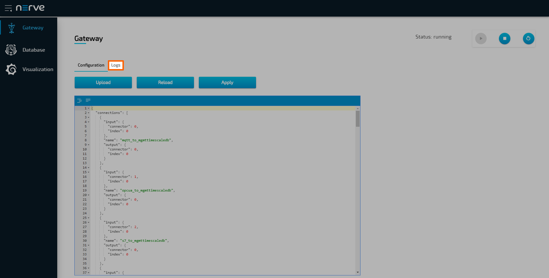
A success notification pops up in the upper-right to confirm that the Gateway has accepted the configuration and everything works as expected. Select the Logs tab to view the Gateway logs for more information.
Verifying the data transmission
The official Microsoft Azure IoT Hub documentation describes multiple ways of verifying if data is being sent from the Nerve node to the Azure IoT Hub device. This example uses a python script utilizing the built-in event hub that is available by default for every created Azure IoT Hub device. This method is valid for every type of Azure subscription, including the free or basic tier. The script is taken from the official Azure sample repository on GitHub. To get it, clone the repository by opening the terminal and running the following command. This requires Git to be installed on the workstation:
git clone https://github.com/Azure-Samples/azure-iot-samples-python
Note
Python version 3.7.0 or higher is required to successfully run the example.
- Navigate to
iot-hub/Quickstarts/read-d2c-messages/inside the cloned repository. - Open the
Readme.mdfile. - Read the instructions carefully.
- Choose either the
read_device_to_cloud_messages_async.pyorread_device_to_cloud_messages_sync.py. This example works with both scripts. -
Replace the placeholder variables below in the chosen script with information from the Event Hub-compatible connection string. This string is obtained when the Azure IoT Hub device is created.
EVENTHUB_COMPATIBLE_ENDPOINTEVENTHUB_COMPATIBLE_PATHIOTHUB_SAS_KEY -
Enter the following command to install the
azure-eventhubpackage:pip install azure-eventhub
-
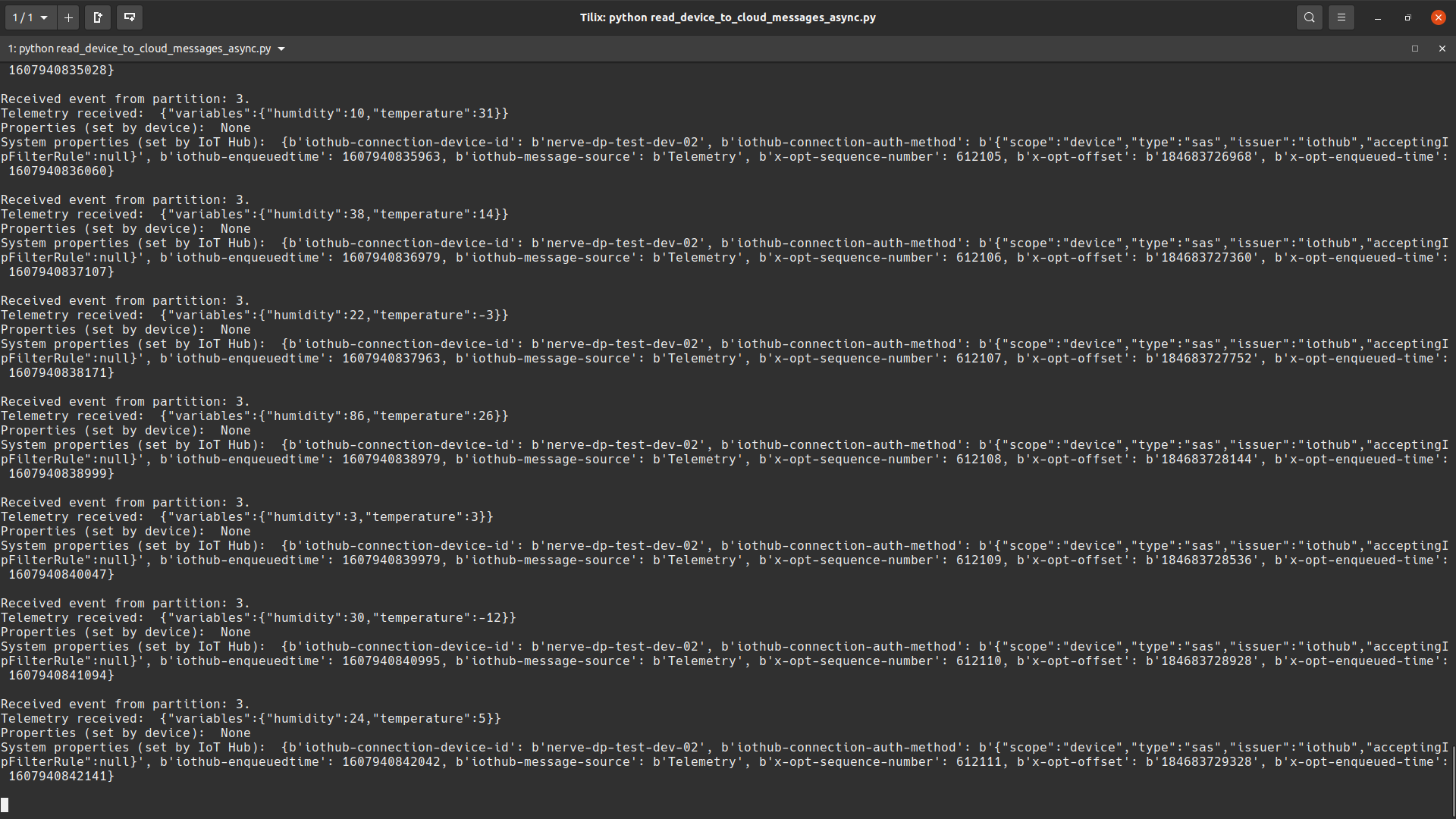
Run the script that was chosen earlier with one of the following commands or executing the file:
python read_device_to_cloud_messages_async.py
or
python read_device_to_cloud_messages_sync.py
The result of the script will look similar to the screenshot below: