Receiving data via MQTT for Analytics and Visualization
In this example, data from a sensor providing temperature and humidity as an MQTT Publisher is visualized and processed via the Data Services and the analytics element. Data will be displayed before and after processing.
The instructions below cover the following steps:
- Provisioning an MQTT broker as a Docker workload
- Provisioning an MQTT Publisher simulation as a Docker workload
- Deploying the provisioned Docker workloads to the target node
- Creating and provisioning an analytics app with the Nerve Data SDK
- Deploying the analytics app as a Docker workload
- Local Data Visualization of temperature data before and after processing
Provisioning and deploying the sensor simulation and the MQTT broker
In the instructions below two Docker workloads will be provisioned and deployed:
An MQTT broker must to be deployed to the node first in order for the sensor simulation to function. The EMQX MQTT broker is used in this example that can be downloaded from the Docker Hub registry.
After that the temperature and humidity sensors simulation MQTT publisher is deployed. Download the Data Services MQTT demo sensor found under Example Applications from the Nerve Software Center. This is the Docker image that is required for provisioning the demo sensor as a Docker workload.
- Log in to the Management System. Make sure that the user has the permissions to access the Data Services.
-
Provision a Docker workload for the EMQX MQTT broker by following Provisioning a Docker workload. This example uses emqx-4.1.0 as the workload name. Use the following workload version settings:
Setting Value Name Enter any name for the workload version. Release name Enter any release name. DOCKER IMAGE Select From registry and enter emqx/emqx:v4.1.0.Container name emqxNetwork name host -
Provision a Docker workload for the sensor simulation by following Provisioning a Docker workload. Use the following workload version settings:
Setting Value Name Enter any name for the workload version. Release name Enter any release name. DOCKER IMAGE Select Upload to add the Docker image of the sensor simulation that has been downloaded before. New environment variable Select the + icon and enter the following information: - Env. variable
MQTT_PUB_TOPIC - Variable value
demo-sensor-topic
Container name ttt-mqtt-demo-sensor-1.0Network name host - Env. variable
-
Deploy both provisioned Docker workloads above by following Deploying a workload.
Preparing the Nerve Data SDK
The Nerve Data SDK is required for working with analytics apps. They are created, built and provisioned with it. Download the Nerve Data SDK found under Nerve Tools from the Nerve Software Center. Refer to Data analytics for more information.
Creating and provisioning an analytics app
Before working with the SDK, make sure that the Conda environment is active. If the Conda environment is active it will be displayed in parentheses in front. The default name of the Conda environment is nerve-dp-analytics. Activate the Conda environment by entering the following command:
source miniconda/bin/activate <environmentname>
The Conda environment automatically deactivates after a restart so it needs to be activated whenever it is used.
-
Enter the following command to create an analytics app.
demo_sensor_analytics_appis the name used for this example:nerve-analytics create demo_sensor_analytics_app .
-
Enter
cd demo_sensor_analytics_appto navigate to the newly created folder. -
Edit the
demo_sensor_analytics_app.pyfile and insert the following code:import signal import sys from nerve_dp_analytics.stream.inputs.input_zeromq import Stream_Input_Zeromq from nerve_dp_analytics.batch.outputs.output_timescaledb import Batch_Output_Timescaledb running = True def sig_hdlr(signal, frame): global running running = False if siz: try: siz.clear() except Exception as e: print(e) if bot: try: bot.clear() except Exception as e: print(e) print('Exiting...') sys.exit(0) # catch CTRL+C signal.signal(signal.SIGINT, sig_hdlr) def celsius_to_kelvin(value): return value + 273.15 def normalize_humidity(value): return value / 100 try: siz = Stream_Input_Zeromq('demo-sensor-analytics-app-siz', host='172.20.10.1', port=5555, topic='demo-sensor-topic') bot = Batch_Output_Timescaledb('demo-sensor-analytics-app-bot', table_name='demo_sensor_analyzed_data', vars={'temperature': 'real', 'humidity': 'real'}) while(running): try: data = siz.receive(Stream_Input_Zeromq.DTYPE_LIST) new_data = list() for d in data: nd = dict() nd['timestamp'] = d['timestamp'] nd['temperature'] = celsius_to_kelvin(d['temperature']) nd['humidity'] = normalize_humidity(d['humidity']) new_data.append(nd) for nd in new_data: bot.send(nd) except Exception as e: print(e) except Exception as e: print(e)
This analytics app receives data from the Gateway through the ZeroMQ Stream Input, which is a default way of transferring data between the Gateway and analytics. Processed data is stored in a TimescaleDB via the TimescaleDB Batch Output. When only
table_nameis provided for this output, the analytics write data into the default database of the node that has the node serial number as a name.In this example, basic processing is done on the data provided by the demo sensor. Temperature data is converted from Celsius to Kelvin while humidity data is normalized to a range between 0 and 1.
Note
The ZeroMQ Publisher output of the Gateway must publish messages on
172.20.10.1if analytics are running on the node in thenerve-dpDocker network. Consequently, the ZeroMQ Stream Input of the analytics must listen on the same IP address. -
Edit the
Dockerfileand insert the following:FROM python:3.8.3-slim-buster WORKDIR /nerve COPY nerve_dp_analytics_api-1.0-py3-none-any.whl . RUN pip install wheel nerve_dp_analytics_api-1.0-py3-none-any.whl WORKDIR / COPY demo_sensor_analytics_app.py . CMD [ "python", "-u", "demo_sensor_analytics_app.py" ]
-
Enter the following command to build the Docker image containing the analytics app.
nerve-dp-2.1.1is used as the name in this example:nerve-analytics build -t nerve-dp-2.1.1
-
Enter the following command to provision the analytics app as a Docker workload in the Management System:
nerve-analytics provision -u https://<MS-URL> -n "Data Services Analytics - demoSensor App" -vn "nerve-dp-2.1.1" -rn "nerve-dp-2.1.1" -desc "Docker container running a Nerve Data Services analytics app that processes temperature and humidity data." -d analytics-demo-sensor-app -i demo_sensor_analytics_app:nerve-dp-2.1.1
This will provision a Docker workload with the following settings:
Setting Description Workload name Data Services Analytics - demoSensor App Description Docker container running a Nerve Data Services analytics app that processes temperature and humidity data. Version name nerve-dp-2.1.1 Release name nerve-dp-2.1.1 CPU resource in percentage 1 Container name analytics-demo-sensor-app Network name nerve-dp Note
Due to version differences, the workload is created with a maximum of 1% of allowed CPU usage. Change this setting to a value between 10 and 25.
All settings except Container name and Network name in the command above or in the Management System are suggestions and can be changed freely.
With the analytics app provisioned in the Management System, the app needs to be deployed to the node to analyze data coming from the demo sensor. Deploy the app to the node that has the demo sensor and the MQTT broker deployed by following Deploying a workload.
Configuring the Data Services Gateway on the node
Now that the demo sensor, the MQTT broker and the analytics app are deployed on the node, the Gateway instance on the node must be configured next in order for data to be processed and visualized.
-
Access the Local UI on the node. This is Nerve Device specific. Refer to the table below for device specific links to the Local UI. The initial login credentials to the Local UI can be found in the customer profile.
Nerve Device Physical port Local UI MFN 100 P1 http://172.20.2.1:3333 Kontron KBox A-150-APL LAN 1 <wanip>:3333
To figure out the IP address of the WAN interface, refer to Finding out the IP address of the device in the Kontron KBox A-150-APL chapter of the device guide.Kontron KBox A-250 ETH 2 <wanip>:3333
To figure out the IP address of the WAN interface, refer to Finding out the IP address of the device in the Kontron KBox A-250 chapter of the device guide.Maxtang AXWL10 LAN1 <wanip>:3333
To figure out the IP address of the WAN interface, refer to Finding out the IP address of the device in the Maxtang AXWL10 chapter of the device guide.Siemens SIMATIC IPC127E X1 P1 http://172.20.2.1:3333 Siemens SIMATIC IPC427E X1 P1 http://172.20.2.1:3333 Supermicro SuperServer E100-9AP-IA LAN1 <wanip>:3333
To figure out the IP address of the WAN interface, refer to Finding out the IP address of the device in the Supermicro SuperServer E100-9AP-IA chapter of the device guide.Supermicro SuperServer 1019D-16C-FHN13TP LAN3 http://172.20.2.1:3333 Supermicro SuperServer 5029C-T LAN1 <wanip>:3333
To figure out the IP address of the WAN interface, refer to Finding out the IP address of the device in the Supermicro SuperServer 5029C-T chapter of the device guide.Vecow SPC-5600-i5-8500 LAN 1 http://172.20.2.1:3333 Winmate EACIL20 LAN1 <wanip>:3333
To figure out the IP address of the WAN interface, refer to Finding out the IP address of the device in the Winmate EACIL20 chapter of the device guide. -
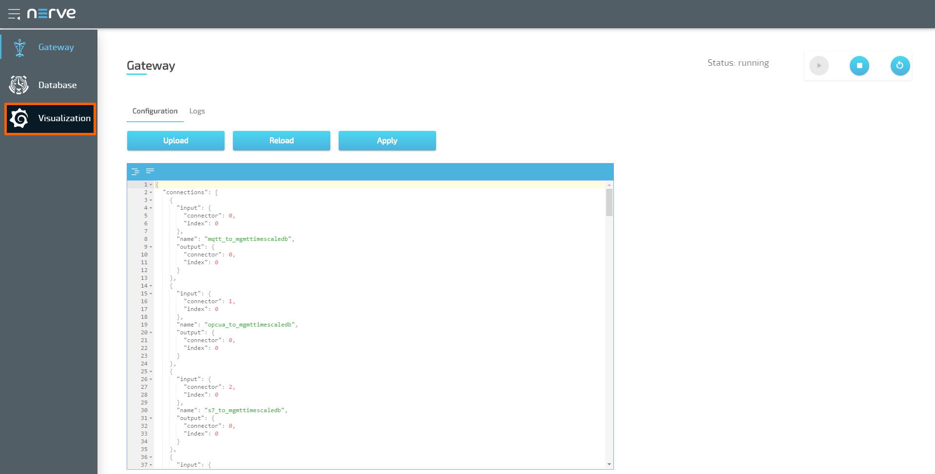
Select Data in the navigation on the left.
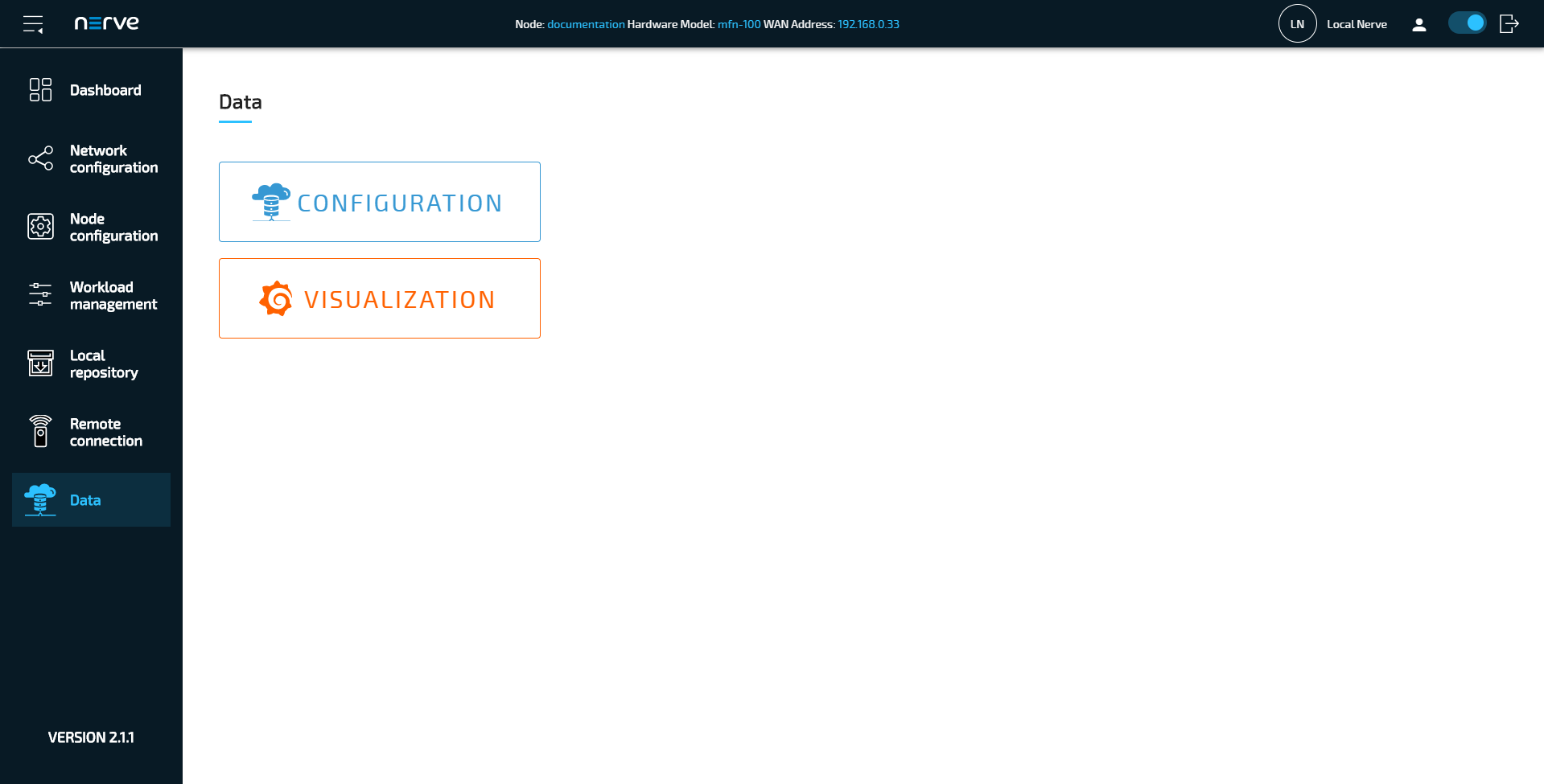
-
Select CONFIGURATION.
-
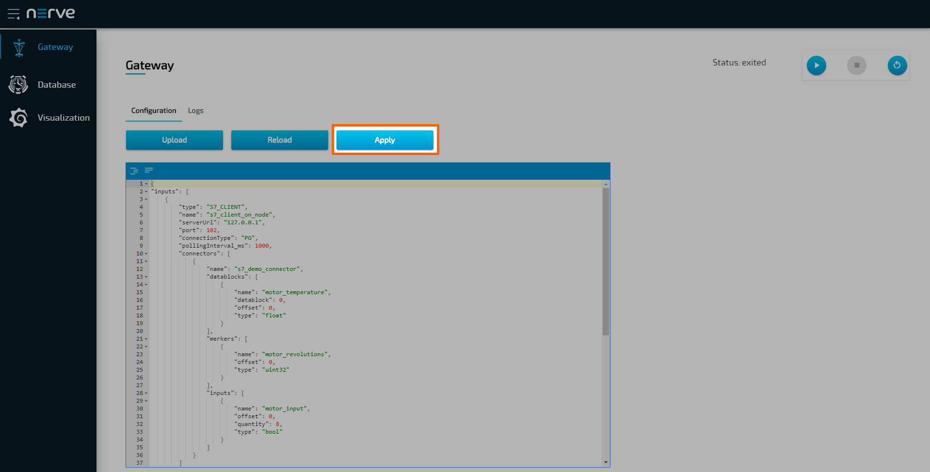
Enter the following configuration into the configuration editor of the Gateway:
{
  "inputs": [
    {
      "type": "MQTT_SUBSCRIBER",
      "name": "mqtt_subscriber",
      "clientId": "mqtt_subscriber_0",
      "serverUrl": "tcp://localhost:1883",
      "keepAliveInterval_s": 20,
      "cleanSession": false,
      "qos": 1,
      "connectors": [
        {
          "name": "mqtt_subscriber_connector_0",
          "topic": "demo-sensor-topic",
          "variables": [
            {
              "name": "temperature",
              "type": "int16"
            },
            {
              "name": "humidity",
              "type": "uint16"
            }
          ]
        }
      ]
    }
  ],
  "outputs": [
    {
      "type": "ZEROMQ_PUBLISHER",
      "name": "zeromq_publisher_0",
      "serverUrl": "tcp://172.20.10.1:5555",
      "connectors": [
        {
          "name": "zeromq_publisher_connector_0",
          "topic": "demo-sensor-topic",
          "timestampRequired": true,
          "timestampFormat": "unix_ns"
        }
      ]
    },
    {
      "type": "DB_TIMESCALE",
      "name": "timescaledb_0",
      "url": "<LOCAL>"
    }
  ],
  "connections": [
    {
      "name": "mqttsub_zmqpub_0",
      "input": {
        "index": 0,
        "connector": 0
      },
      "output": {
        "index": 0,
        "connector": 0
      }
    },
    {
      "name": "mqttsub_timescaledb_0",
      "input": {
        "index": 0,
        "connector": 0
      },
      "output": {
        "index": 1,
        "connector": 0
      }
    }
  ]
}
-
Select Apply to save the Gateway configuration. The Gateway will restart automatically.
This configuration defines an MQTT Subscriber connection to a ZeroMQ Publisher. Upon receiving data from the demo-sensor-topic topic of the MQTT Subscriber, the Gateway forwards said data to the ZeroMQ Publisher. The ZeroMQ Publisher in turn publishes the data to the demo-sensor-topic ZeroMQ topic that the analytics app listens to. The configuration also defines a connection from the MQTT Subscriber to the TimescaleDB database, which means that the same data received at the MQTT Subscriber end is also written directly into the TimescaleDB.
Note
Note that both topics have the same name in this example. However, they are different as they are topics of two different protocols, MQTT and ZeroMQ.
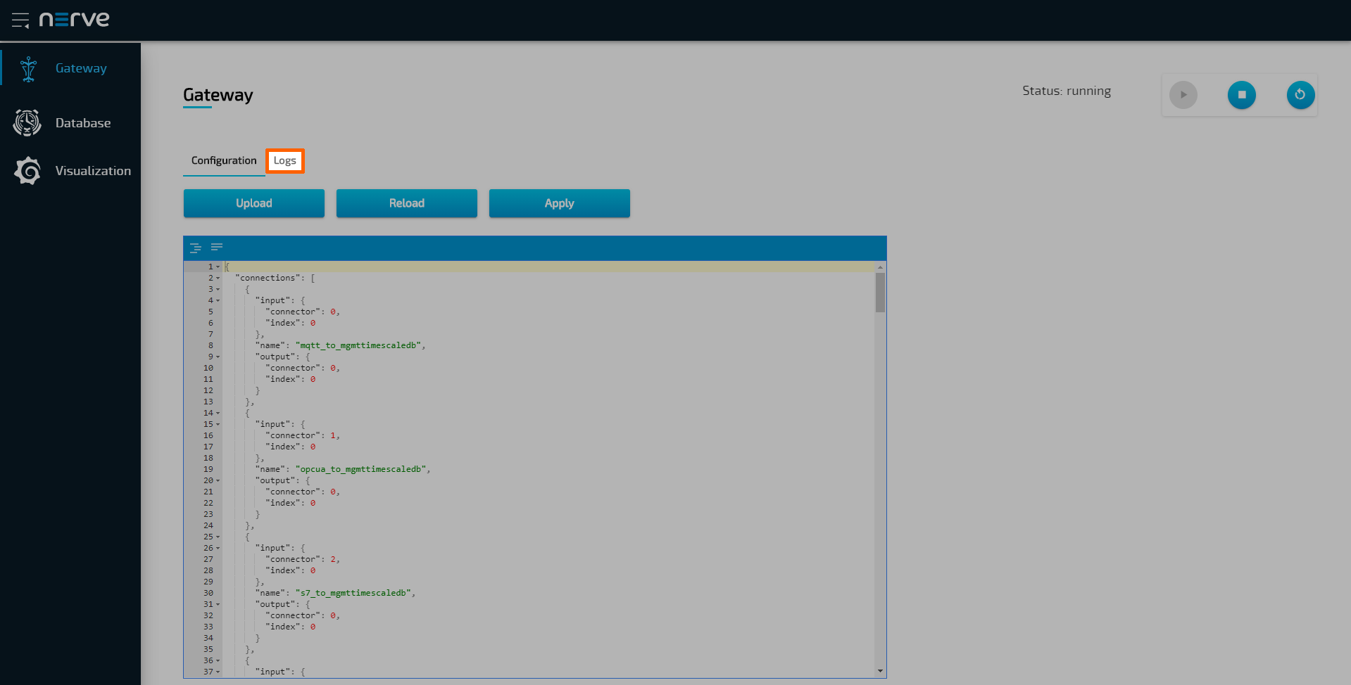
A success notification pops up in the upper-right to confirm that the Gateway has accepted the configuration and everything works as expected. Select the Logs tab to view the Gateway logs for more information.
Local data visualization at the node
To visualize the data received by the Gateway and data processed by the analytics app, open the local data visualization element through the Data Services UI on the node. Two queries will be added in the instructions below.
-
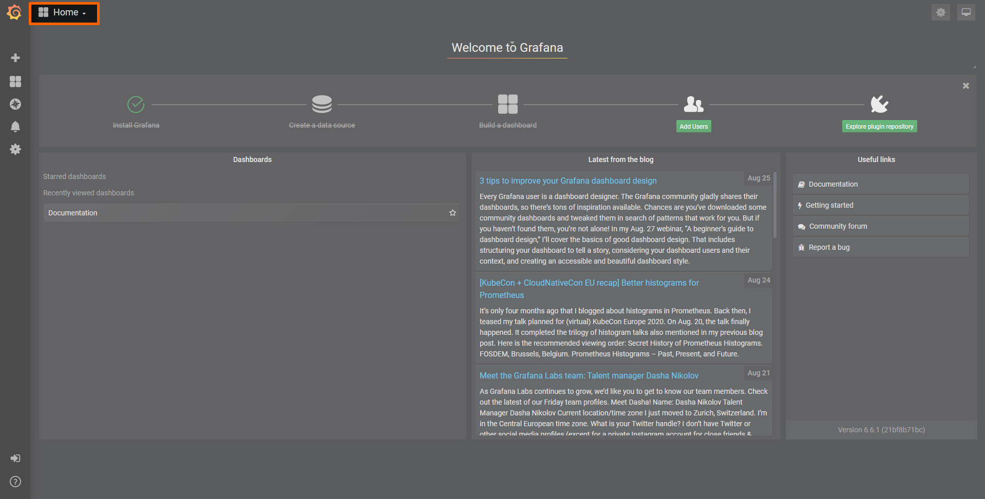
Select Visualization in the navigation on the left. The Grafana UI will open.
-
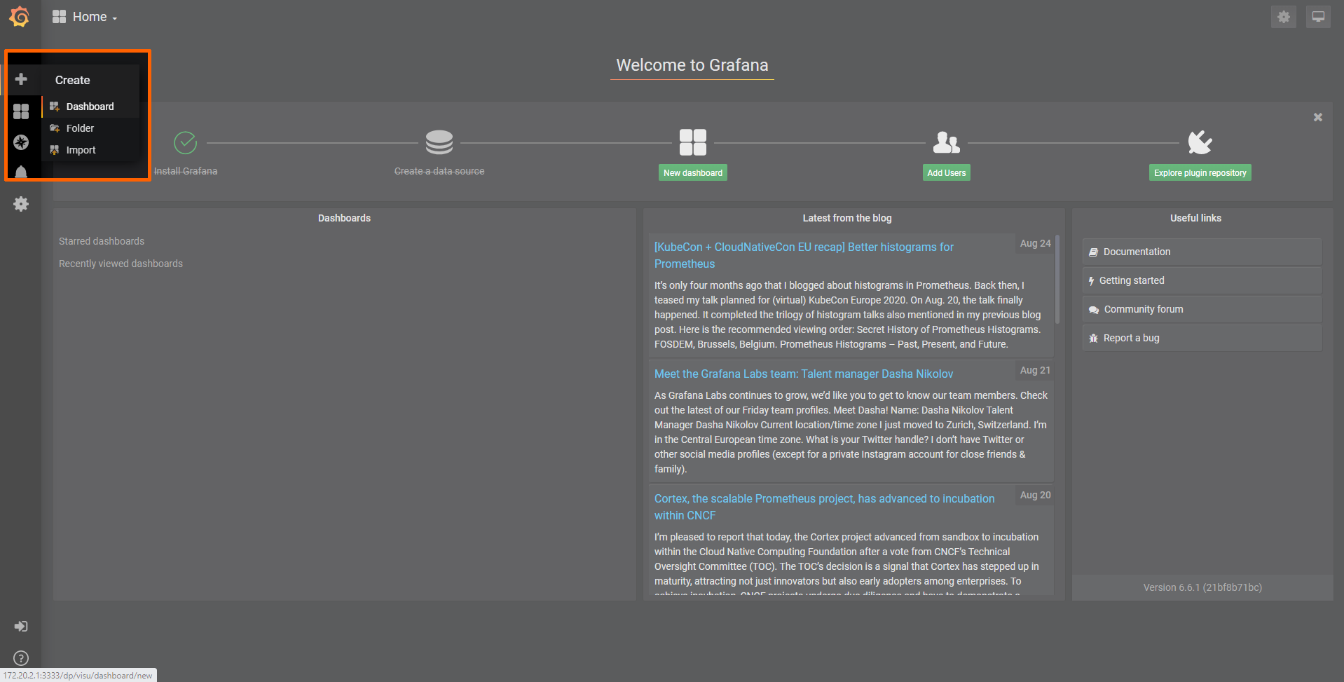
Select + > Dashboard in the navigation on the left. A box will appear.
-
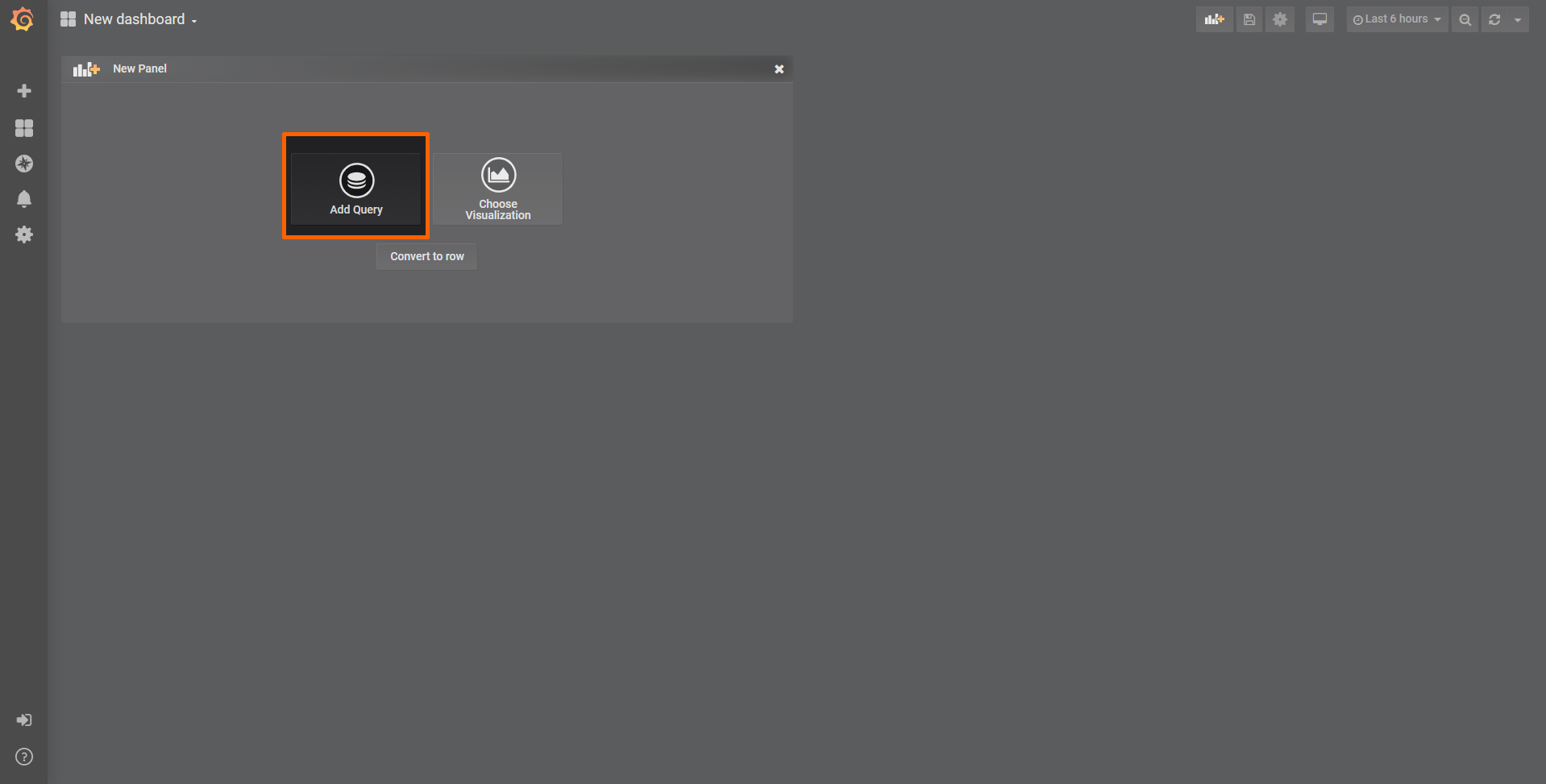
Select Add Query in the New Panel box.
-
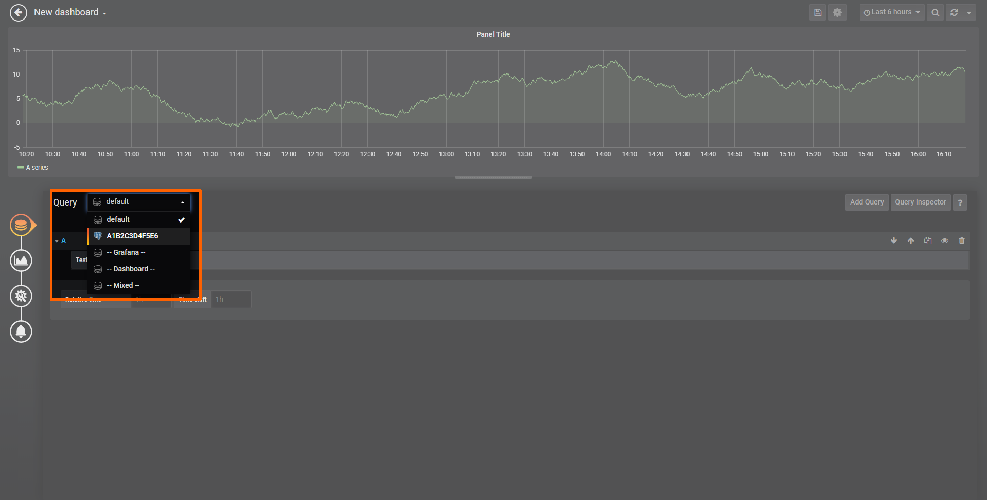
Select the data source from the drop-down menu. The name of the data source is the serial number of the node.
-
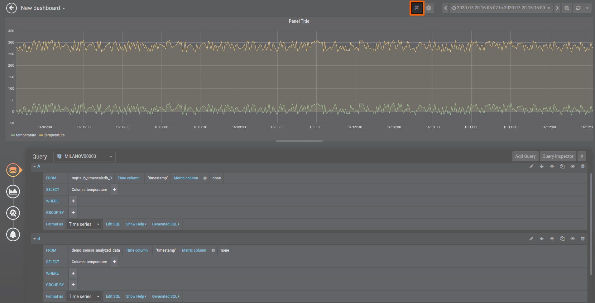
Fill in the following query information to add the temperature data from the MQTT Subscriber:
Setting Value FROM mqttsub_timescaledb_0
Time column: "timestamp"SELECT Column: temperature Format as Time series -
Select Add Query to the right to add query B for temperature data analyzed by the analytics app.
-
Fill in the following query information:
Setting Value FROM demo_sensor_analyzed_data
Time column: "timestamp"SELECT Column: temperature Format as Time series -
Select the save icon in the upper-right corner to save the dashboard.
The dashboard can be accessed from the Grafana home menu.