Connecting new sensors and actuators
Add sensors and actuators to the kit to execute control applications and visualize the corresponding data. With the delivered set-up it is possible to add up to 7 additional inputs and outputs. I/O blocks can also be added to increase the number or type of inputs and outputs.
Wiring a new sensor or actuator
Note
- Before wiring any new components, review the Nerve Blue Kit Circuit Diagram. Contact a sales representative for more information.
- Disconnect the power supply from the power outlet before wiring new I/O devices to prevent injury to persons or damage to equipment.
- Only staff with knowledge about electrical circuits should perform the tasks described in this section.
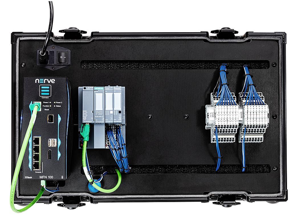
The inputs and outputs of the SIMATIC ET200 SP I/O module are wired to the terminal blocks on the right hand side of the kit. The left terminal block is used to connect digital inputs. The right terminal block is used to connect digital outputs.
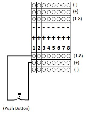
Connecting a digital input
This section shows how to connect an additional digital input to the kit. A push button is used for demonstration purposes.
- Connect the power supply of the button to the middle row of the I/O module (+24V).
-
Connect the input to the top row.
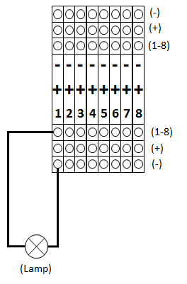
Connecting a digital output
This section shows how to connect an additional digital output to the kit. A lamp is used for demonstration purposes.
- Connect the lamp to the top row of the I/O module.
-
Connect the common wire to the bottom row to close the electrical circuit.
After wiring the sensors or actuators to the inputs or outputs respectively switch the kit back on.
The next chapter describes how to assign variables to the inputs and outputs in order to read data from newly connected sensors or control actuator functionality.