Data transfer from CODESYS to the Management System
Note
The configuration and visualization of new variables with the Nerve Datapath and Grafana is not available in version 2.0 of Nerve Blue. This chapter covers steps and information before the visualization is configured. The Nerve Datapath and Grafana visualization will be available with version 2.1.
The kit sends data that is generated in CODESYS from the MFN 100 to the Management System using variables. The kit has a pre-configured Gateway configuration for the Data Services that can be further configured to send new values to the Management System. This chapter gives a quick overview on how to configure new variables.
Overview
The CODESYS runtime has an integrated OPC UA server which can be configured via the CODESYS Development System. The data from the OPC UA server is received by an OPC UA client, ingested by the Data Services and written into the database in the Management System.
The Data Services are pre-configured to transmit a set of different kinds of CODESYS variables to the Management System. Use the following global variables to transmit data to the Management System:
| Global Variables | |||
|---|---|---|---|
BOOL_1 |
Integer_1 |
Real_1 |
STRING_1 |
BOOL_2 |
Integer_2 |
Real_2 |
STRING_2 |
BOOL_3 |
Integer_3 |
Real_3 |
STRING_3 |
BOOL_4 |
Integer_4 |
Real_4 |
STRING_4 |
BOOL_5 |
Integer_5 |
Real_5 |
STRING_5 |
The following instructions are only needed if new variables are added or a completely new CODESYS project is created.
Configuring the CODESYS OPC UA server
In the CODESYS Development System it is possible to configure which variables are available in the OPC UA server. Configuring variables requires an object called Symbol Configuration.
- Open a CODESYS project to configure variables.
- Expand Device (Nerve_MFN_100) > PLC Logic.
- Right click Application.
- Select Add Object.
-
Click Symbol Configuration...

-
Tick Support OPC UA Features.

-
Click Add.
Adding variables to the OPC UA server
Before adding variables to the OPC UA server, add the object Symbol Configuration to the tree structure. Refer to the instructions above on how to add the Symbol Configuration to the tree structure.
- Open a CODESYS project to configure variables.
- Expand Device (Nerve_MFN_100) > PLC Logic > Application.
- Double-click Symbol Configuration.
-
Click Build.

-
Expand GVL.
-
Tick the variables to add to the OPC UA server.

Adding variables to the Data Services Gateway
The instances of the Nerve Data Services Gateway on the node and in the Management System have a pre-configured Gateway configuration loaded. These configurations need to be adapted when new values are added through sensors, actuators and in the CODESYS Development System.
Local Data Services Gateway on the node
- Connect the workstation to the console port P1 of the MFN 100.
-
Configure the network adapter through which the workstation is connected to the MFN 100 the following way:
IP address 172.20.2.90Subnet mask 255.255.255.0 -
Follow this link to reach the Local UI: http://172.20.2.1:3333.
- Log in with the credentials from the customer profile.
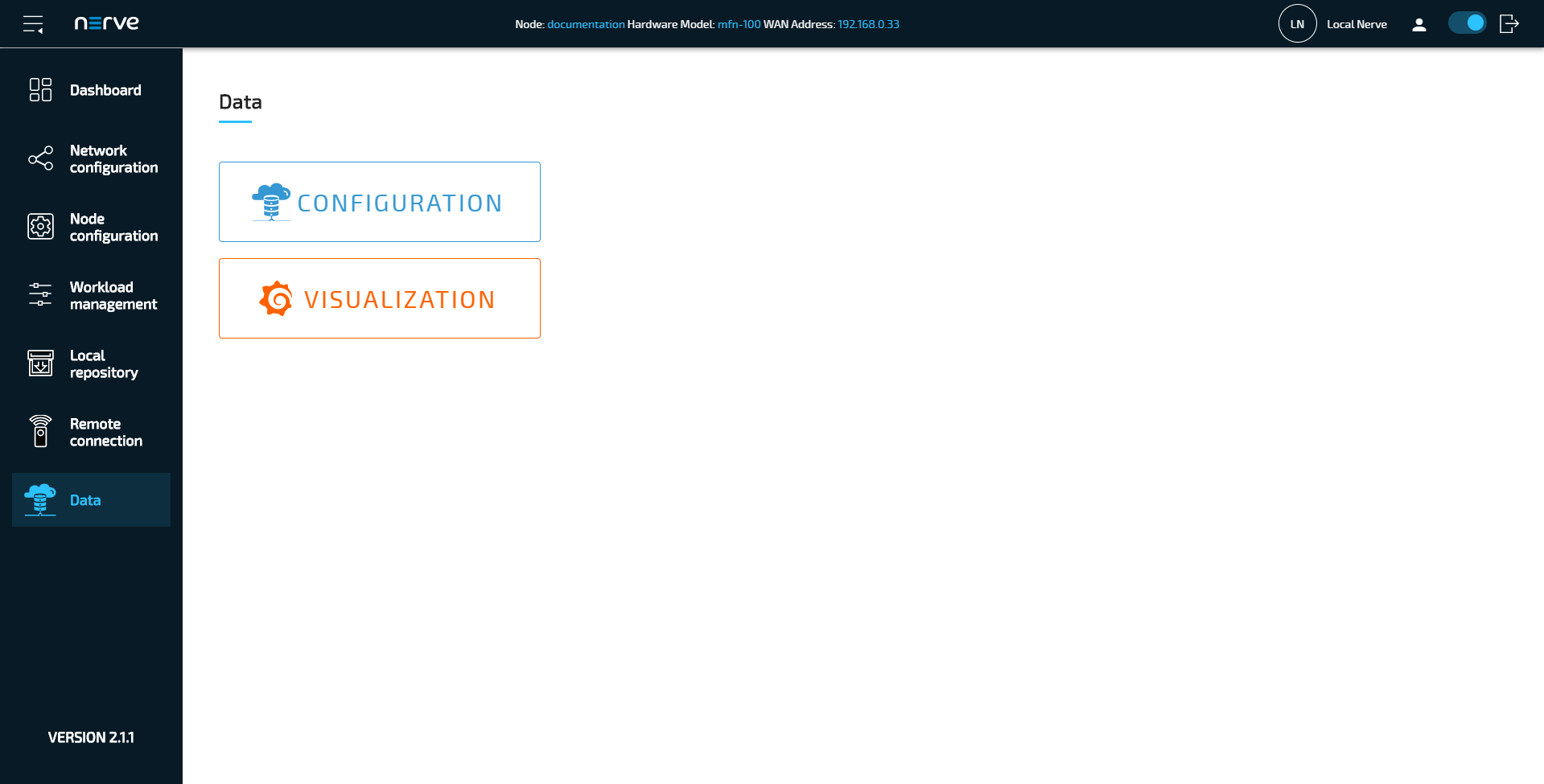
- Select Data in the navigation on the left.
-
Select CONFIGURATION.
-
Look for the following part of the currently loaded Gateway configuration:
"samplingIntervalAtServer_ms": 500,
 "nodes": [
    "ns=4;s=|var|Nerve_MFN_100 .Application.GVL.iCountButton",
    "ns=4;s=|var|Nerve_MFN_100 .Application.GVL.iCountNumber",
    "ns=4;s=|var|Nerve_MFN_100 .Application.GVL.BOOL_1",
    "ns=4;s=|var|Nerve_MFN_100 .Application.GVL.BOOL_2",
    "ns=4;s=|var|Nerve_MFN_100 .Application.GVL.BOOL_3",
    "ns=4;s=|var|Nerve_MFN_100 .Application.GVL.BOOL_4",
    "ns=4;s=|var|Nerve_MFN_100 .Application.GVL.BOOL_5",
    "ns=4;s=|var|Nerve_MFN_100 .Application.GVL.Integer_1",
    "ns=4;s=|var|Nerve_MFN_100 .Application.GVL.Integer_2",
    "ns=4;s=|var|Nerve_MFN_100 .Application.GVL.Integer_3",
    "ns=4;s=|var|Nerve_MFN_100 .Application.GVL.Integer_4",
    "ns=4;s=|var|Nerve_MFN_100 .Application.GVL.Integer_5",
    "ns=4;s=|var|Nerve_MFN_100 .Application.GVL.Real_1",
    "ns=4;s=|var|Nerve_MFN_100 .Application.GVL.Real_2",
    "ns=4;s=|var|Nerve_MFN_100 .Application.GVL.Real_3",
    "ns=4;s=|var|Nerve_MFN_100 .Application.GVL.Real_4",
    "ns=4;s=|var|Nerve_MFN_100 .Application.GVL.Real_5",
    "ns=4;s=|var|Nerve_MFN_100 .Application.GVL.STRING_1",
    "ns=4;s=|var|Nerve_MFN_100 .Application.GVL.STRING_2",
    "ns=4;s=|var|Nerve_MFN_100 .Application.GVL.STRING_3",
    "ns=4;s=|var|Nerve_MFN_100 .Application.GVL.STRING_4",
    "ns=4;s=|var|Nerve_MFN_100 .Application.GVL.STRING_5"
-
Edit the last line the following way to add a new variable called
myVar1:"ns=4;s=|var|Nerve_MFN_100 .Application.GVL.STRING_2", "ns=4;s=|var|Nerve_MFN_100 .Application.GVL.STRING_3", "ns=4;s=|var|Nerve_MFN_100 .Application.GVL.STRING_4", "ns=4;s=|var|Nerve_MFN_100 .Application.GVL.STRING_5", "ns=4;s=|var|Nerve_MFN_100 .Application.GVL.myVar1"
The variable is added as a fully qualified nodeId. Refer to Unified Automation for more information.
Note
This NodeId can be found out with an OPC UA Client such as UA Expert. Connect a workstation to P1 of the MFN 100 and connect to
opc.tcp://172.20.2.2:4840in the OPC UA Client. -
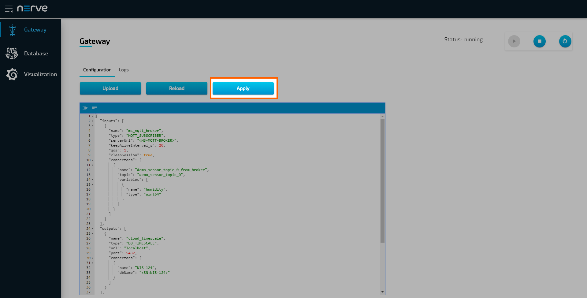
Select Apply to save the Gateway configuration. The Gateway will restart automatically.
![!Apply Gateway configuration]../img/data_opcua-ms01.png)
The data is automatically stored in the local TimescaleDB and also sent to the Management System. Refer to Nerve Data Services for more information.
Central Data Services Gateway in the Management System
- Log in to the Management System
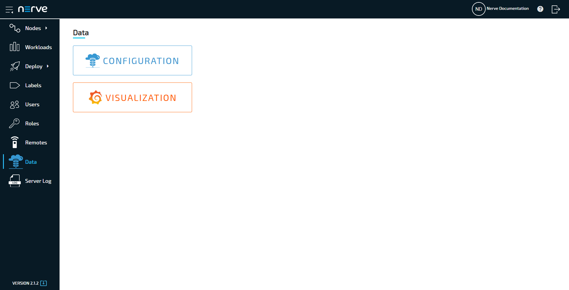
- Select Data in the navigation on the left. Make sure that the user has the necessary permissions to access the Data Services.
-
Select CONFIGURATION to access the Data Services UI.
-
Look for the following part of the currently loaded Gateway configuration:
{ "name": "STRING_1", "type": "string" }, { "name": "STRING_2", "type": "string" }, { "name": "STRING_3", "type": "string" }, { "name": "STRING_4", "type": "string" }, { "name": "STRING_5", "type": "string" } -
Edit the last line the following way to add a new variable called
myVar1:{ "name": "STRING_1", "type": "string" }, { "name": "STRING_2", "type": "string" }, { "name": "STRING_3", "type": "string" }, { "name": "STRING_4", "type": "string" }, { "name": "STRING_5", "type": "string" }, { "name": "myVar1", "type": "bool" }Note
Note that the type of the variable is determined when the new variable is configured in the CODESYS Development System.
-
Select Apply to save the Gateway configuration. The Gateway will restart automatically.
Visualizing new variables
Newly added variables can also be visualized through the visualization element of the Data Services. The instructions below describe how to add new variables to the existing dashboard by adding a query. New dashboards can also be created for the new variables. Refer to Creating a dashboard for more information.
Adapting the local data visualization on the node
- Connect the workstation to the console port P1 of the MFN 100.
-
Configure the network adapter through which the workstation is connected to the MFN 100 the following way:
IP address 172.20.2.90Subnet mask 255.255.255.0 -
Follow this link to reach the Local UI: http://172.20.2.1:3333.
- Log in with the credentials from the customer profile.
- Select Data in the navigation on the left.
-
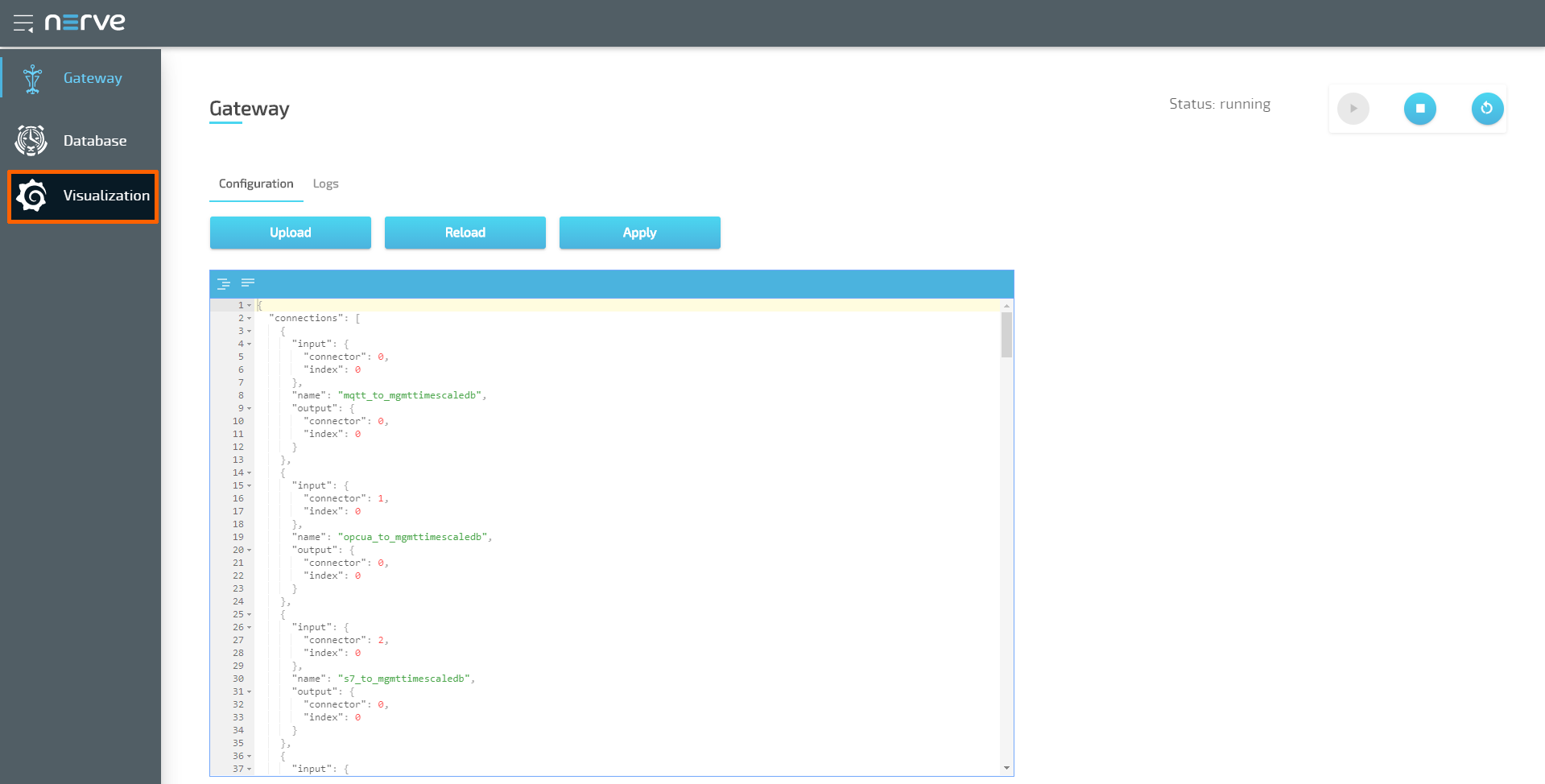
Select VISUALIZATION.
Note
The visualization element can also be reached from the Data Services UI. When in the Data Services UI, select Visualization in the navigation on the left and select Open to reach the Grafana UI.
-
Select Home in the upper-left corner.
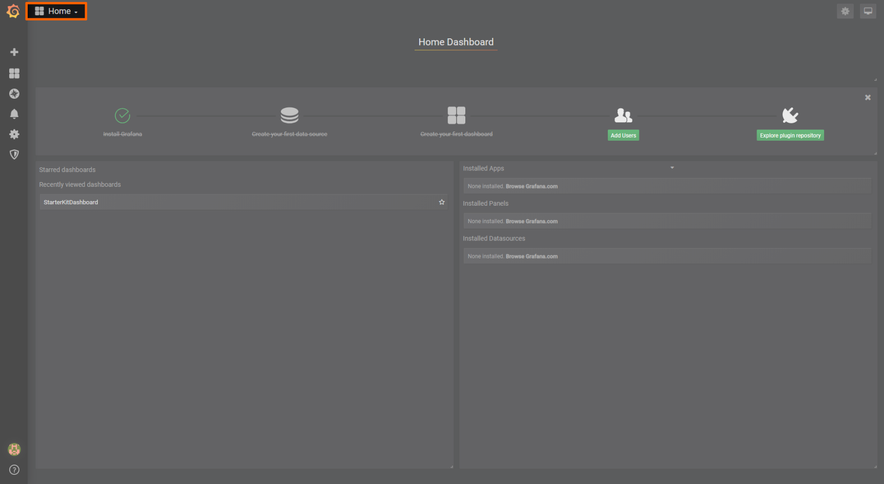
-
Select Nerve Blue Kit underneath the search bar.
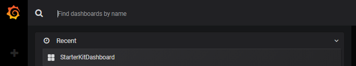
-
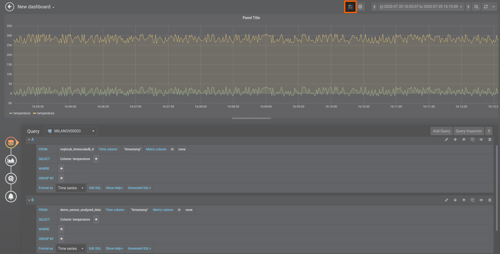
Select Add Query to the right to add a query for the new variable.
-
Fill in the following query information:
Setting Value FROM Codesys_to_localdb
Time column: "timestamp"SELECT Column: myVar1 Format as Time series -
Select the save icon in the upper-right corner to save the dashboard.
Adapting the central data visualization in the Management System
- Log in to the Management System.
-
Select Data in the navigation on the left.
Note
If the menu item Data is not available, make sure the logged in user has the permission to access the Data Services. Refer to Assigning a role to a user for more information.
-
Select VISUALIZATION.
Note
The visualization element can also be reached from the Data Services UI. When in the Data Services UI, select Visualization in the navigation on the left and select Open to reach the Grafana UI.
-
Select Home in the upper-left corner.
-
Select Nerve Blue Kit underneath the search bar.
-
Select Add Query to the right to add a query for the new variable.
-
Fill in the following query information:
Setting Value FROM ms_mqtt_broker_to_cloud_timescale_db
Time column: "timestamp"SELECT Column: myVar1 Format as Time series -
Select the save icon in the upper-right corner to save the dashboard.