Local UI
The Local UI is provided by a web server that is running locally on the Nerve Device. Compared to the Management System, the Local UI covers features that only concern the node itself.
The Local UI gives access to the following features:
- Network configuration
- Node registration and password management
- Workload management
- Local workload deployment
- Local workload repository
- Management of remote connections
Connecting to the Local UI
Connecting to the Local UI depends on the Nerve Device. Refer to the table below on how to reach the Local UI for each Nerve Device. Make sure to connect a workstation to the physical port of the Nerve Device associated with host access and configure the network adapter of the workstation. The IP address has to be in the same range as the IP address of the host access interface with a 255.255.255.0 subnet mask.
| Nerve Device | Physical port | Local UI |
|---|---|---|
| MFN 100 | P1 | http://172.20.2.1:3333 |
| Kontron KBox A-150-APL | LAN 1 | <wanip>:3333To figure out the IP address of the WAN interface, refer to Finding out the IP address of the device in the Kontron KBox A-150-APL chapter of the device guide. |
| Kontron KBox A-250 | ETH 2 | <wanip>:3333To figure out the IP address of the WAN interface, refer to Finding out the IP address of the device in the Kontron KBox A-250 chapter of the device guide. |
| Maxtang AXWL10 | LAN1 | <wanip>:3333To figure out the IP address of the WAN interface, refer to Finding out the IP address of the device in the Maxtang AXWL10 chapter of the device guide. |
| Siemens SIMATIC IPC127E | X1 P1 | http://172.20.2.1:3333 |
| Siemens SIMATIC IPC427E | X1 P1 | http://172.20.2.1:3333 |
| Supermicro SuperServer E100-9AP-IA | LAN1 | <wanip>:3333To figure out the IP address of the WAN interface, refer to Finding out the IP address of the device in the Supermicro SuperServer E100-9AP-IA chapter of the device guide. |
| Supermicro SuperServer 1019D-16C-FHN13TP | LAN3 | http://172.20.2.1:3333 |
| Supermicro SuperServer 5029C-T | LAN1 | <wanip>:3333To figure out the IP address of the WAN interface, refer to Finding out the IP address of the device in the Supermicro SuperServer 5029C-T chapter of the device guide. |
| Vecow SPC-5600-i5-8500 | LAN 1 | http://172.20.2.1:3333 |
| Winmate EACIL20 | LAN1 | <wanip>:3333To figure out the IP address of the WAN interface, refer to Finding out the IP address of the device in the Winmate EACIL20 chapter of the device guide. |
Once a connection is established, log in with the credentials for the Local UI to reach the Local UI dashboard.

Local UI dashboard
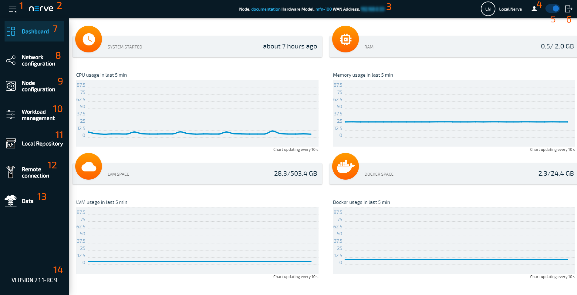
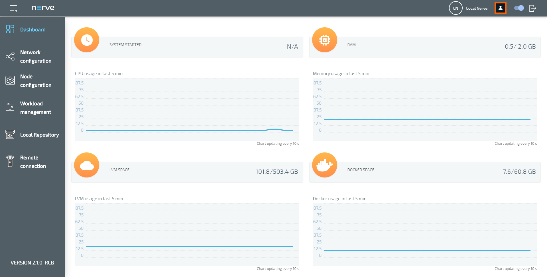
The dashboard of the Local UI is the default screen after the log in. Usage statistics of the Nerve Device are displayed in the window with more options in the menu on the left side.
| Term | Description |
|---|---|
| Burger menu (1) | Expand and collapse the left-hand menu by clicking here. |
| Nerve logo (2) | Click here to return to the dashboard and reload the page. |
| Node details (3) | Details of the node are displayed here, showing the name of the node in the Management System, the hardware model and the WAN address of the node. |
| Change password (4) | Clicking here leads to an area where the password to the Local UI can be changed. |
| Connect button (5) | Select the slider here to disconnect the node from the network. Blue indicates an active connection to the network. If the button is white, then the node is offline. |
| Log out (6) | Click here to log out of the Local UI. |
| Dashboard (7) | Select this to display the dashboard containing the system metrics — graphs showing available resources of the Nerve Device and their usage over time. |
| Network configuration (8) | This menu allows to configure the Ethernet ports of the Nerve Device. |
| Node configuration (9) | Configure data such as the Management System URL that the node will connect to or the serial number of the node here. The information required to register a node in the Management System is configured in this menu. Also, passwords can be changed here. |
| Workload management (10) | Select this menu for control options for deployed workloads and manual deployment of workloads. |
| Local Repository (11) | Find settings for the configuration of a local workload repository here. |
| Remote connection (12) | Manage incoming and active remote connections here. |
| Data (13) | Access the instance of the Nerve Data Services in the Local UI here. Refer to Nerve Data Services for more information. |
| Node version (14) | This is the currently installed version of the node. |
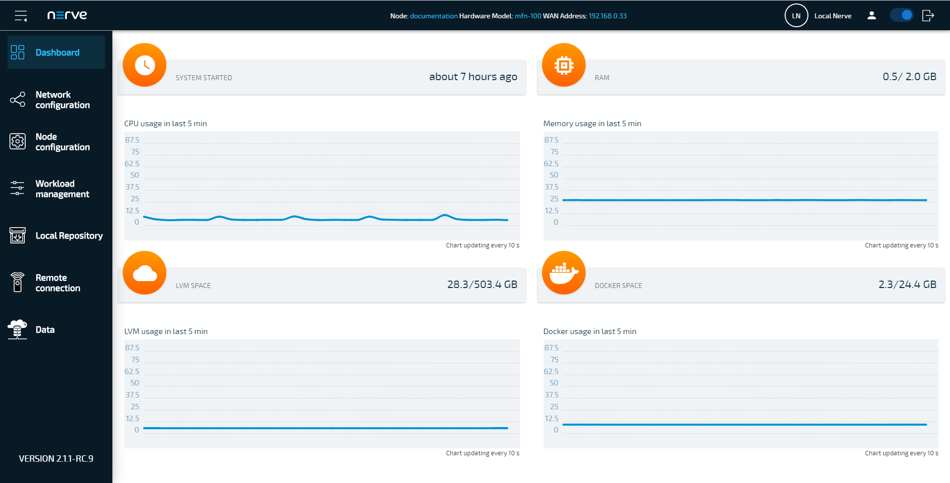
System metrics
The graphs in the Local UI dashboard show available resources of the Nerve Device and their usage over time. The y-axis displays percentages and the x-axis is updated every 10 seconds, showing a time span of 5 minutes. The percentages displayed are always in relation to the maximum of the available resource:
| Item | Description |
|---|---|
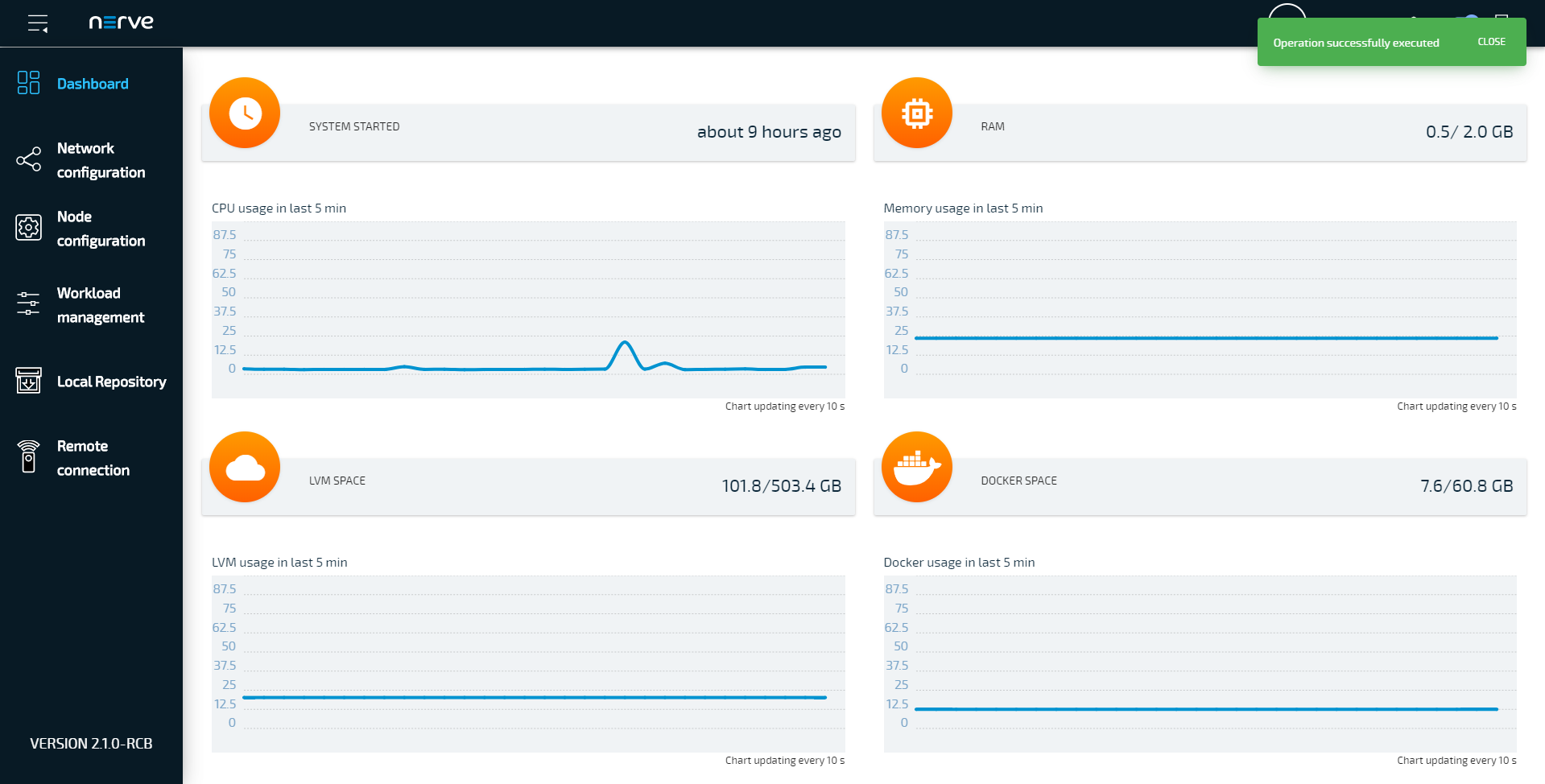
| SYSTEM STARTED | This shows how long the Nerve Device has been running. If the device is restarted, this value is reset. |
| CPU usage in last 5 min | The graph here shows the percentage of processing power that is being used. This includes CPUs that have been assigned to VMs and Docker containers. |
| RAM | This shows how much memory is used (left value) and how much memory is available in total (right value). Example: 0.3/1.9 GB Note that the total amount of memory the Nerve Device offers is not shown here. This is the memory that is available for the host. |
| Memory usage in last 5 min | Similar to CPU usage, the graph shows the percentage of memory used. This includes memory that has been assigned to VMs or Docker containers. |
| LVM SPACE | Virtual machines have their dedicated virtual partition (Logical Volume Manager). The values show how much of this partition is used (left value) and how much is available in total (right value). Example: 86.5/238.5 GB |
| LVM usage in the last 5 min | This graph shows the percentage of space that is being used by the Logical Volume Manager. |
| DOCKER SPACE | Similar to LVM space, Docker containers have their dedicated virtual partition. The values show how much of this partition is used (left value) and how much is available in total (right value). Example: 2.9/40.3 GB |
| Docker usage in the last 5 min | This graph shows the percentage of space for Docker containers that is being used. |
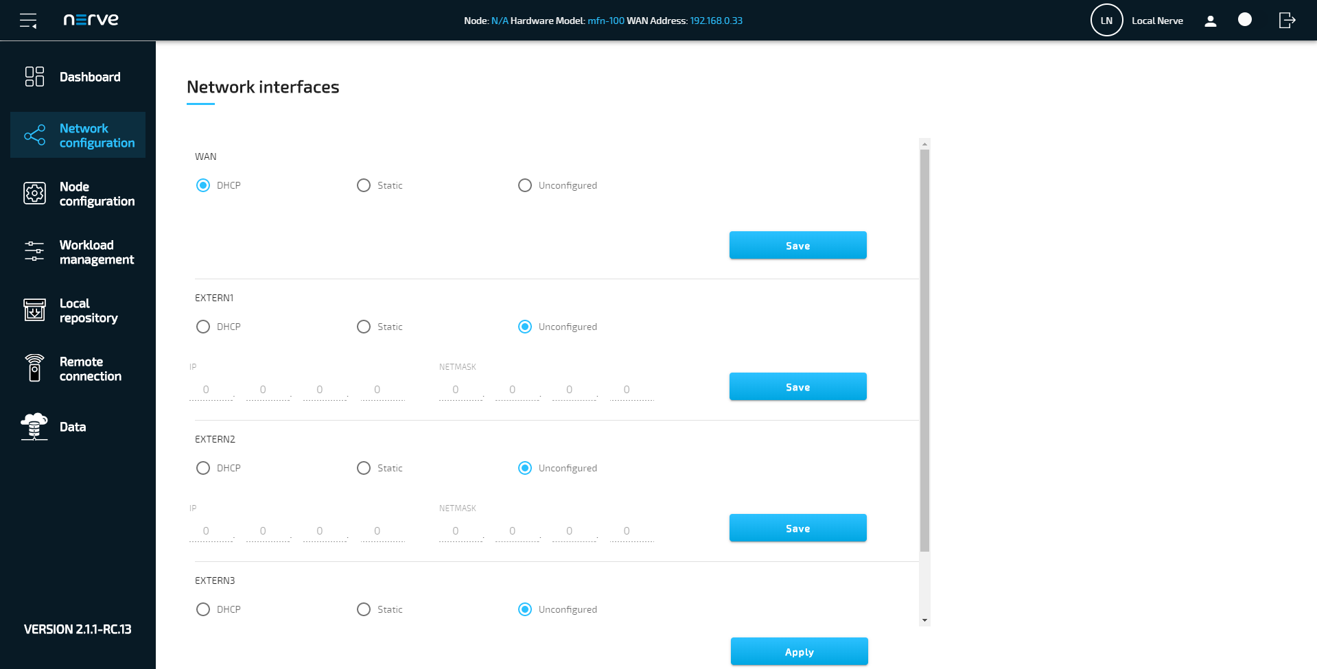
Local network configuration
From the Local UI, the Ethernet ports of the Nerve Device can be configured. Select Network configuration in the navigation on the left to reach this menu. The example below is of the MFN 100. The page is specific to the Nerve Device. The number and names of interfaces may differ.
| Item | Description |
|---|---|
| DHCP | The IP address of the port will be assigned by the DHCP server. If an IP address has been assigned, it will be displayed here. |
| Static | By selecting Static, the IP address of the port needs to be manually defined. Enter the IP address and subnet mask under IP and NETMASK to set a static IP address. For the WAN interface, the GATEWAY, the preferred DNS as well as two alternative DNS can also be set.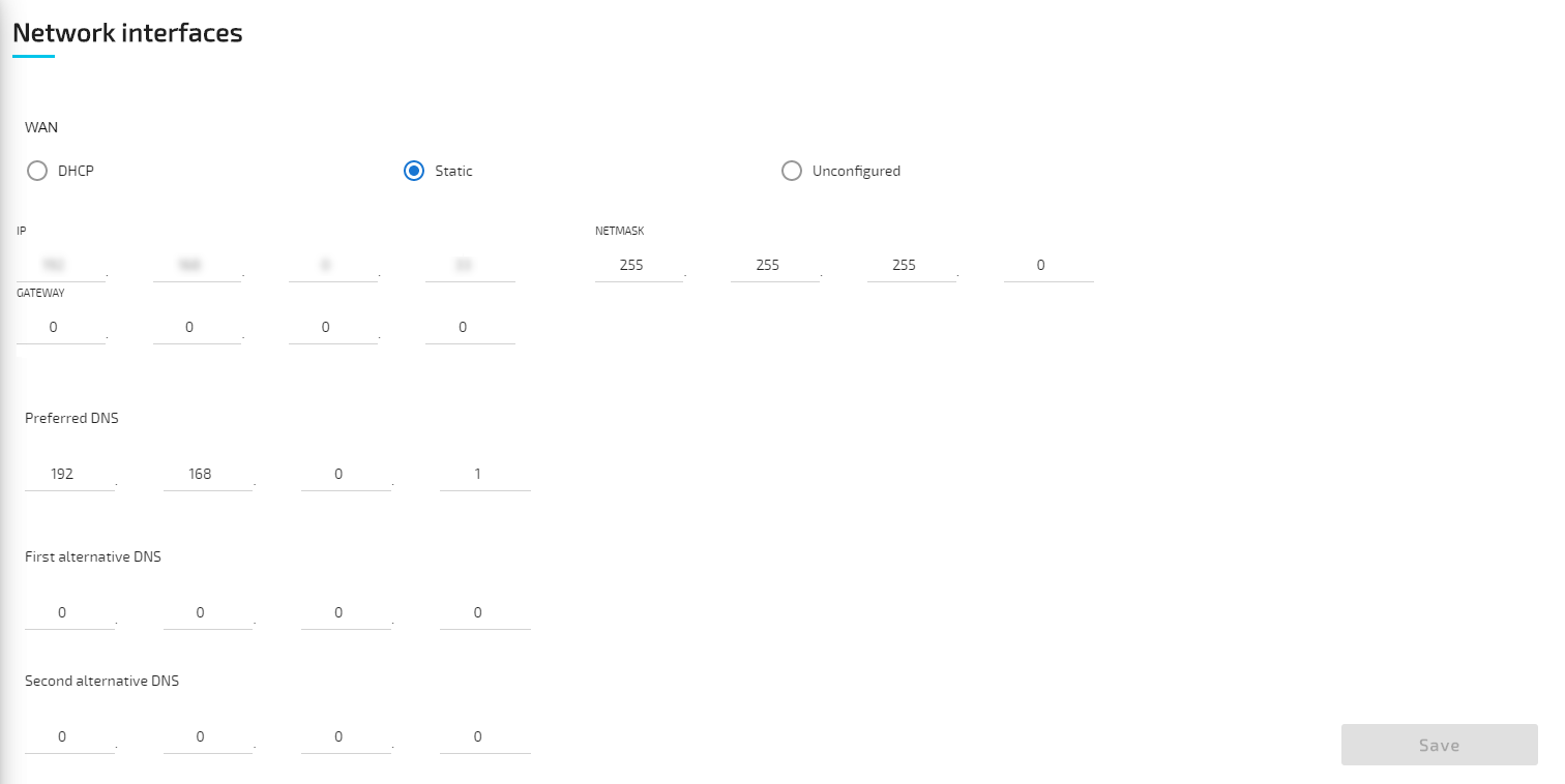 |
| Unconfigured | If Unconfigured is checked, the port is disabled for the host but can still be used for virtual machines with bridged interfaces. |
Note
For more information on networking and interfaces refer to the networking chapter.
Proxy settings
Network configuration settings can be extended with the possibility to specify proxy settings. In case a proxy server is present in the company network, these settings can be used to enable communication between the node and the Management System. The proxy settings define an HTTP/S proxy for the node with the possibility to specify credentials if they are requested, as well as exceptions. Note that the proxy settings affect the internal communication of the node towards the Management System, and the connections covered by the proxy settings are only those related to:
- the management of workloads on the node
- logs sent from the node to the Management System
- data transmitted from the Data Services Gateway
Potential connections generated by workloads on the node do not use the node proxy settings.
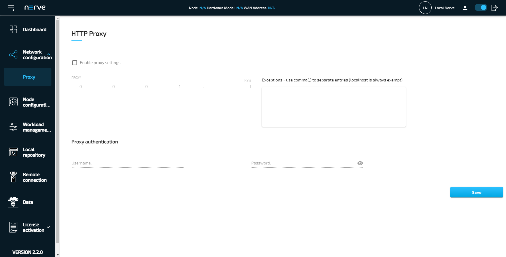
Expand Network configuration > Proxy to reach the proxy settings.
| Item | Description |
|---|---|
| Enable proxy settings | Tick the checkbox here to enable proxy settings. |
| PROXY | Enter the IP address of the proxy server here. |
| PORT | Enter the number of the port that is open for communication at the proxy server. |
| Exceptions - use comma(,) to separate entries (localhost is always exempt) | List IP addresses or hostnames of exceptions separated by a comma here. The node will directly communicate with the exceptions without using the proxy server. An example is a local workload repository that can be defined in the Local UI. Refer to Setting a local repository for more information. |
| Proxy authentication | Enter the Username and Password required to access the proxy server. This is optional. If the proxy server does not require login credentials, the fields can be left empty. |
Select Save to apply the configuration. To undo the proxy settings, uncheck Enable proxy settings and select Save.
Node configuration
The first part of registering a node in the Management System is performed in the Local UI. Node details and information required for registering a node in the Management System are configured under Node configuration.
- Select Node configuration in the navigation on the left.
-
Enter the following information:
Protocol Select wss or ssl from the drop-down menu: - wss
Selecting this will use the WebSocket Secure protocol for the registration of the node, meaning that port 443 will be used for communication between the node and the Management System. - ssl
Selecting this will use the Secure Sockets Layer protocol for the registration of the node, meaning that port 8883 will be used for communication between the node and the Management System.
Note that port 8883 of the company firewall has to be open when using the SSL protocol.
Cloud URL Enter the URL of the Management System without the protocol, e.g example.nerve.cloud.Serial number Enter a serial number with a minimum of 12 characters.
Note that this serial number can be freely defined. It is required for node registration in the Management System and serves as a means of identification. Entering the serial number that is printed on the Nerve Device is not required but recommended. - wss
-
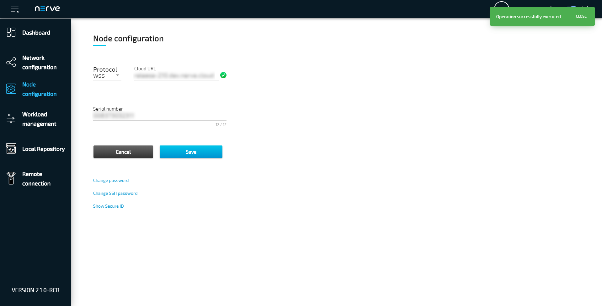
Click Save.
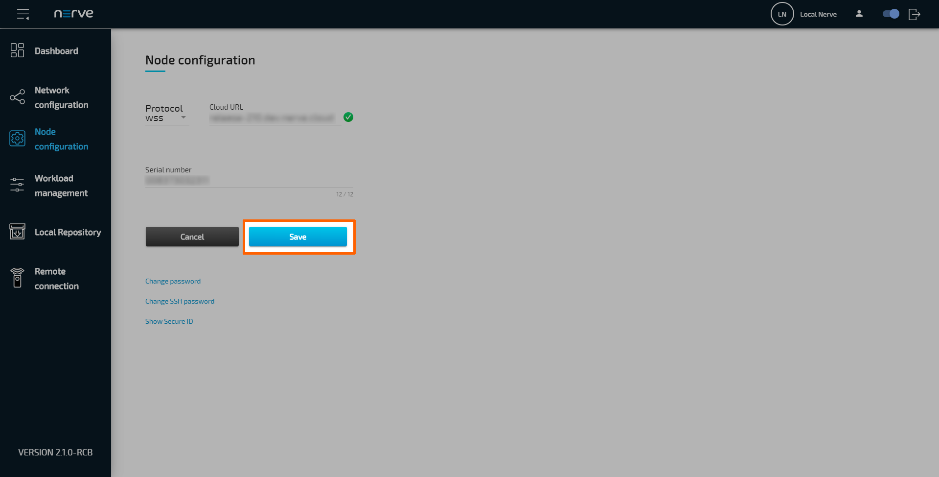
With the serial number saved in the node configuration, the secure ID has been generated and can be displayed by selecting Show Secure ID. This secure ID is required when adding the node in the Management System. Refer to Adding a node on how to add nodes to the Management System.
Changing the password for host access
The password for host access via SSH can be changed. The default password for host access is found in the customer profile. Changing the host access password makes it persist through version updates. If the default password is not changed, updating the node to a newer version will change the host access password to a new default.
Note
Access to the Linux host system of Nerve Blue is provided in order to enable advanced use cases. Using host access requires expert Linux knowledge as system internal changes can be performed. Note that changes may impact the Nerve Blue system.
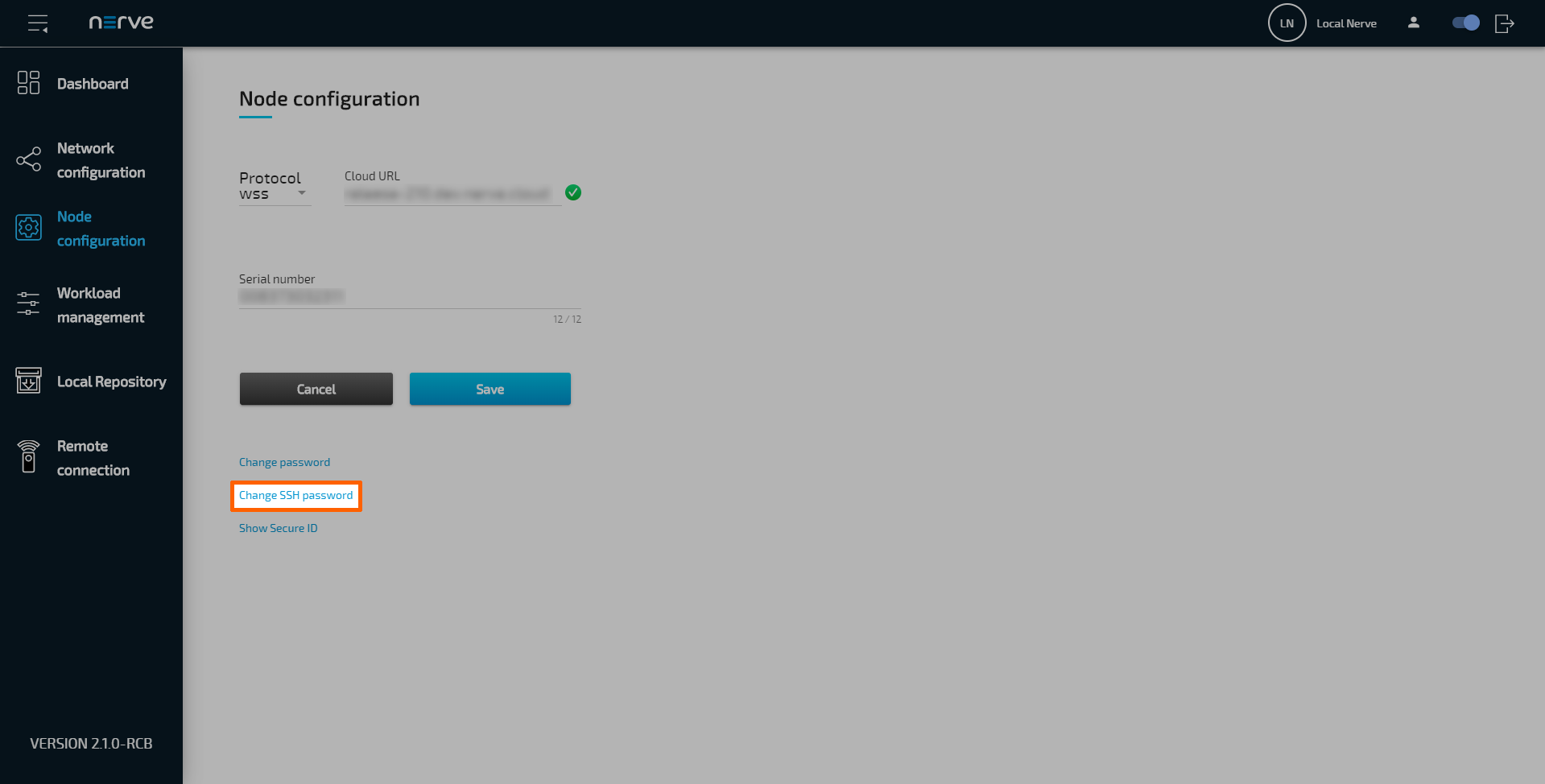
- Select Node configuration in the navigation on the left.
-
Select Change SSH password
-
Enter the following information:
Item Description Old password Enter the old password for host access. New password Enter the new password here. The new password must be 8 characters or longer and it can only consist of alphanumeric characters. Confirm new password Enter the new password again. Both passwords must match in order to proceed. -
Select Save to set the new password.
If the process was successful, the Local UI will display the dashboard with a green notice confirming the change in the upper-right corner.
Changing the password for the Local UI
The password to the Local UI can be changed. The default password for Local UI access can be found in the customer profile. Changing the password to the Local UI makes it persist through version updates. If the default password is not changed, updating the node to a newer version will change the Local UI password to a new default.
-
Select the user icon (Change password) in the upper-right.
Note
Alternatively, it is also possible to change the password in the Node configuration menu. Select Node configuration in the navigation on the left and click Change password to reach the password form.
-
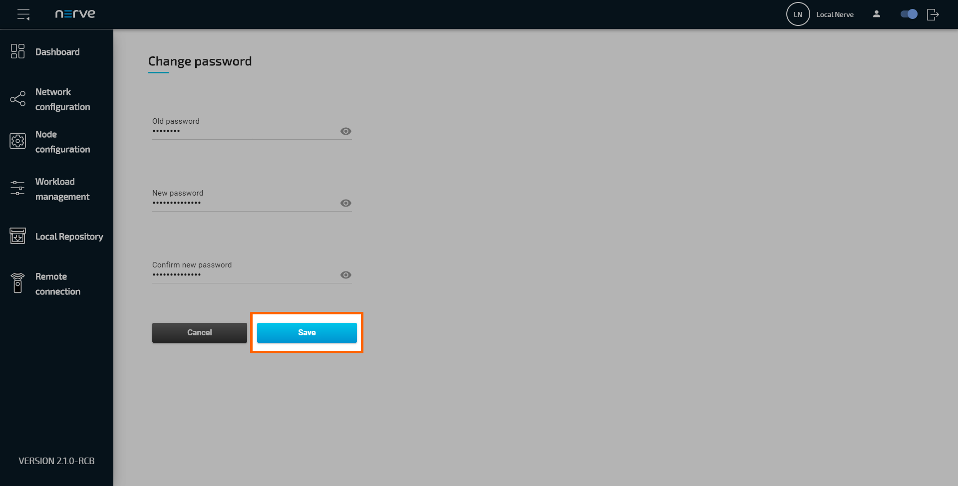
Enter the following information:
Item Description Old password Enter the old password to the Local UI. New password Enter the new password here. The new password must be 8 characters or longer and it can only consist of alphanumeric characters. Confirm new password Enter the new password again. Both passwords must match in order to proceed. -
Select Save to set the new password.
If the process was successful, the Local UI will display the dashboard with a green notice confirming the change in the upper-right corner.
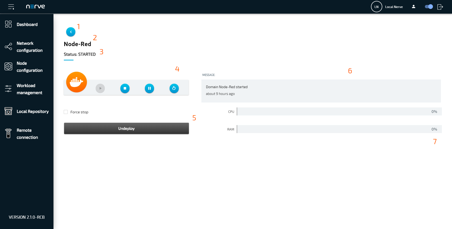
Workload management
Deployed workloads can be controlled in the Local UI. Select Workload management in the navigation menu on the left-hand side for an overview of all deployed workloads. Then, select a workload to reach the interface for controlling workloads running on the Nerve Device. If there is a large number of workloads deployed, filter the list by name or by type. Enter a search query under Search by name to filter the list by name. Select All, VM, Codesys and Docker from the drop-down menu to filter workloads by type.

Note that CODESYS workloads can only be controlled in the Local UI, as operation of a CODESYS workload may have an impact on machine operation and therefore should not be controlled remotely. Virtual machine workloads and Docker workloads can also be controlled in the Management System. Refer to the workload control section in the node tree chapter on how to control workloads in the Management System.
| Item | Description |
|---|---|
| Back button (1) | Click here to return to overview of workloads. |
| Workload name (2) | This is the name of the workload. The name of the workload version is not displayed. |
| Workload status (3) | The current status of the workload is displayed here. The possible statuses are the following:
|
| Control panel (4) | There are five control options for workloads here:
Also, stopping a CODESYS workload will reset it to its initial values unless the CODESYS application has been written using the retain variables library. Refer to Enabling retain variables for more information. |
| Undeploy (5) | Clicking here removes the workload from the node. To deploy the workload again, it has to be deployed through the Local UI or the Management System. |
| Message window (6) | The message window displays the latest message the workload has sent out including how much time has passed since it was sent out. The type of message that is displayed here depends on the workload. Here is a list of messages that are valid for VMs and Docker containers:
For VMs, there is an additional set of messages:
CODESYS workloads have the following set of messages:
|
| Usage statistics (7) | Virtual Machine workloads and Docker workloads have their assigned resources they can use. The use of these resources is displayed with bar graphs:
|
All changes performed in the Local UI are reflected in the Management System.
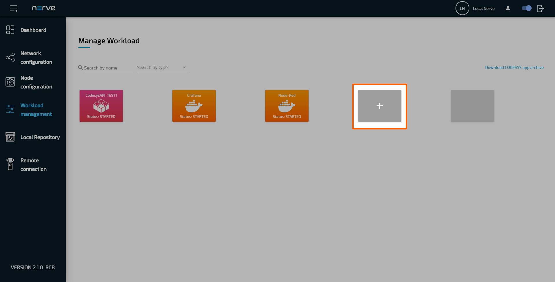
Local workload deployment
Workloads that have been provisioned in the Management System can be exported and then deployed directly through the Local UI. Refer to the workloads chapter on how to export a workload before following the instructions below.
- Export a workload in the Management System.
- Switch to the Local UI.
- Select Workload management in the navigation on the left side.
-
Click the plus tile in the middle.
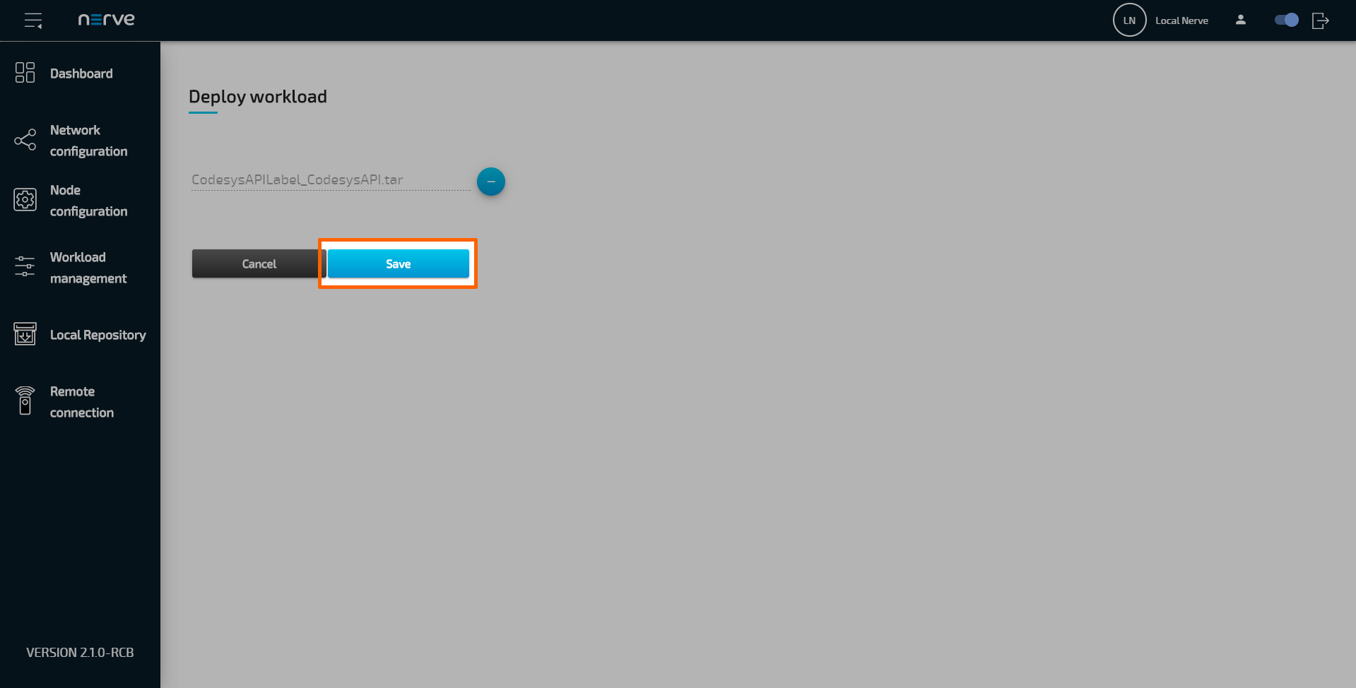
-
Select the plus symbol to open the file browser.
- Add the TAR file containing the exported workload.
-
Select Save to deploy the workload.
Setting a local repository
If desired, the required files for deploying workloads can be stored in a local repository that does not require internet connection. In doing so, the workload image files for deployment are taken from a user defined repository instead of the workload repository in the Management System.
Refer to Exporting a Workload for information on how to obtain the workload images. Also note that every workload needs to be provisioned in the Management System once before the image files can be transferred to a local repository.
A web server that services static files is required. Popular web servers like Nginx or Apache HTTP Server can be used, as well as a Network-attached storage (NAS) device. Recommended are:
- the NodeJS http-server for Linux
- the built-in Internet Information Services (IIS) for Windows
The IIS for Windows needs to be activated first in newer versions of Windows like Windows 8 and Windows 10.
- Open the Control Panel
- Navigate to Control Panel > Programs > Programs and Features.
- Select Turn Windows features on or off
- Tick the checkbox next to Internet Information Services.
Note that ticking the checkbox will only enable the components required to publish a web site. Expand the folder to select other needed features. - Select OK.
With this the IIS can be used on a Windows machine. Take the following steps to enable the hosting of the workload images. The steps below are not carried out in detail as they are only serving as a guideline.
- Remove all files from the document root. The default location of the document root is
C:\inetpub\wwwroot. - Copy the TAR files of the workloads that have been exported from the Management System to the document root.
- Enable directory listing.
- Test the web server by opening http://localhost in a web browser.
- Test if a computer can be reached from another computer in the network.
Note
Note that all served files can be accessed from all computers connected to the same network.
For more information, refer to the IIS documentation. Follow the instructions below to enable a local repository for a node:
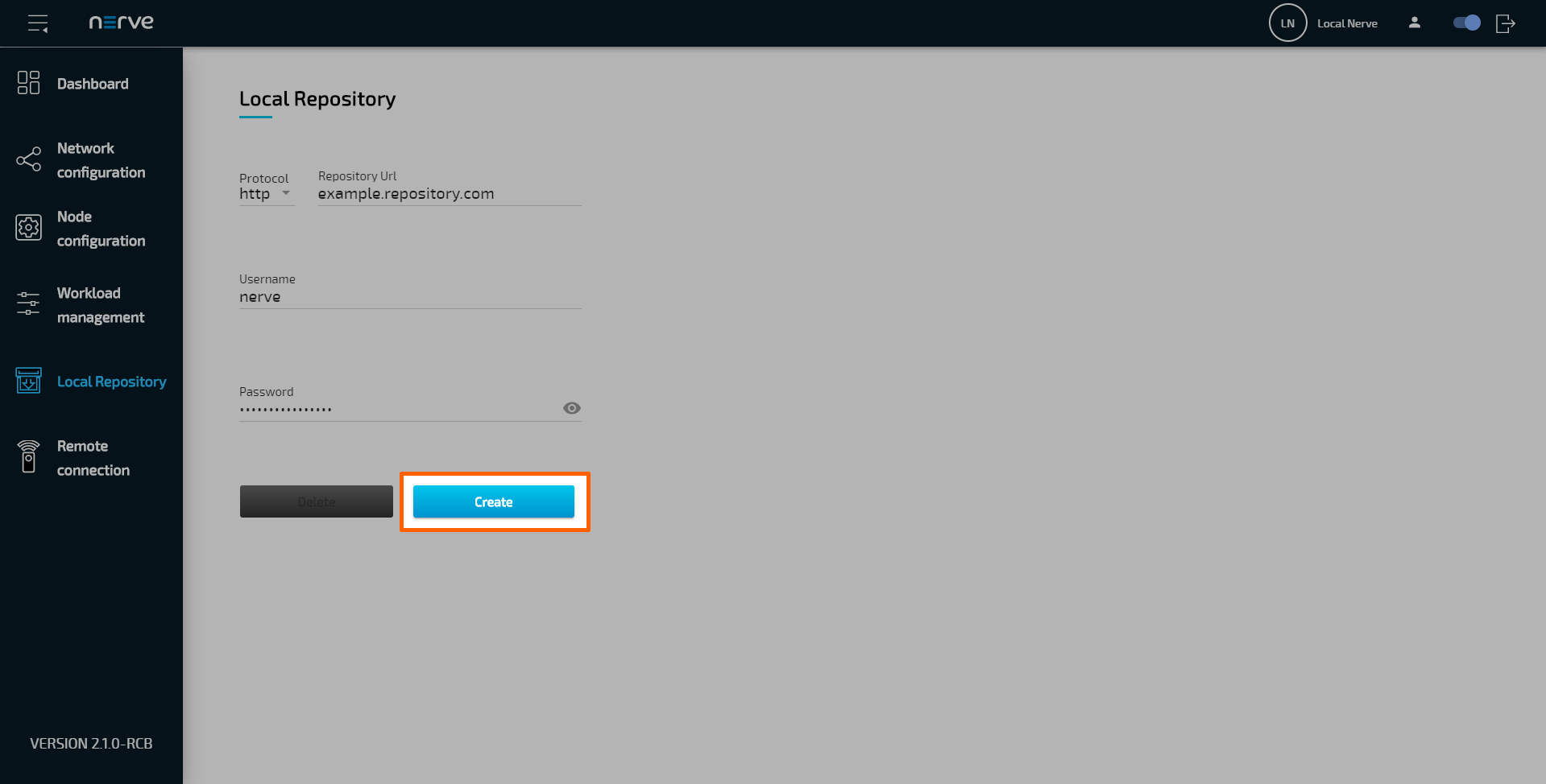
- Select Local Repository in the navigation on the left.
-
Enter the following information:
Protocol Select the protocol for communication with the local repository: http or https. Repository URL Enter the URL through which the web server hosting the workload images can be accessed. Username If login credentials have been defined for the web server, enter the username for accessing the web server hosting the workload images. Password If login credentials have been defined for the web server, enter the password for accessing the web server hosting the workload images. -
Select Create to finish the setup.
If a local repository is defined in the Local UI, the Management System will look for the workload images in the local repository first when a workload is deployed to this node. If the workload image is not present in the local repository, the workload repository in the Management System will be used instead. To revert back to using the repository of the Management System, select Local Repository in the navigation on the left and select Delete.
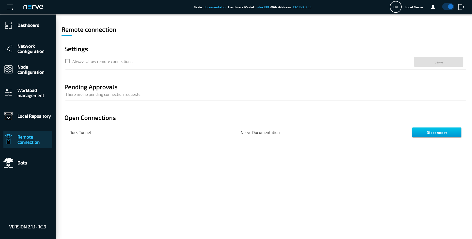
Managing remote connections
The behavior of nodes for remote connections is defined when a remote connection is configured in the Management System. Refer to Remote connections for more information.
| Settings | Tick the checkbox next to Always allow remote connections to automatically approve all remote connection requests. This setting is only valid when Local acknowledgment is set to Yes in the remote connection configuration in the Management System. |
| Pending Approvals | Incoming connection requests are displayed here. Select Approve to accept the remote connection. Clicking Cancel denies the incoming request. This setting is only valid when Local acknowledgment is set to Yes in the remote connection configuration in the Management System. |
| Open Connections | Connection requests that have been approved and are currently open are listed here. To the left, the name of the remote connection is shown. This name is also shown under Remotes in the Management System. In the middle, the user that established the remote connection is displayed. To the right, there is a button to terminate the remote connection. |
Approving a remote connection
Local approval for remote connections can be configured in the Management System. Set Local acknowledgment to Yes when configuring a remote connection. When set to Yes, every remote connection has to be approved in the Local UI before it can be established. If approval for an incoming remote connection is pending, a notification bubble appears next to Remote connections in the navigation on the left.
- Select Remote connections in the navigation on the left.
- Search for incoming remote connections under Pending Approval.
-
Click Approve on the right for the remote connection that shall be established.
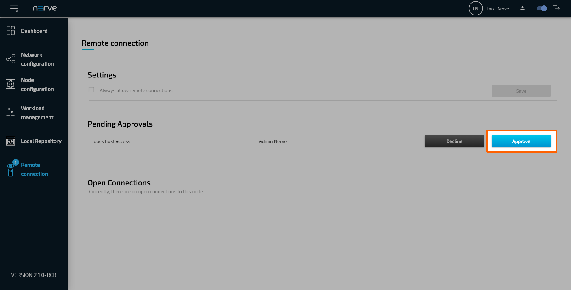
Once approved, the open connection will be displayed under Open Connections below. Shown are the name of the remote connection and the user that is currently using the remote connection. If the same remote connection is used by multiple users, multiple entries of the same remote connection are shown with different users.