MFN 100
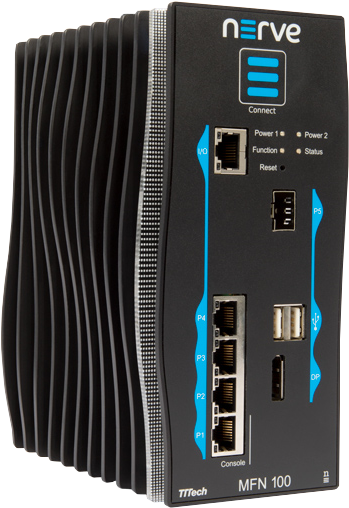
The MFN 100 is a qualified Nerve Device that is optimized and tested for use with Nerve software. The device is designed for use in harsh industrial environments (-40°C to +70°C). It is based on an Intel Atom x5-E3940/50 CPU and offers 4 GB/8 GB RAM and up to 512 GB SSD storage. The MFN 100 offers one I/O port for Ethernet-based fieldbus connectivity, four GbE switch ports and one SFP port. Additional interfaces include two USB 2.0 ports and one DisplayPort.
Technical data
| CPU | Intel E3940 4 cores, 1.8 GHz, 4 GB RAM Intel E3950 4 cores, 2.0 GHz, 8 GB RAM |
| Storage | 64 GB SSD MLC 256 GB SSD MLC 512 GB SSD MLC |
| Performance | 1 ms control cycle time achievable with Nerve Blue |
| Interfaces |
|
| Mounting | DIN rail or wall mount |
| Dimensions | (h x w x d): 179 x 87 x 143 mm |
| Weight | 2.1 kg |
| Power | 2 x 24 V redundant input, Average power consumption 12 W |
| Environmental Parameters |
|
| Certificates | CE and UL certified (EN 61000-6-2/4, IEC/UL 61010, CSA C22.2 NO. 61010-1-12) |
Identifying the MFN 100
The label of the MFN 100 can be found on the back of the device, close to the DIN rail clip. Exact identification is possible through the combination of product number (P/N), serial number (S/N) and version number (V/N) that are printed on the label. The model number of the MFN 100 details the variant of the MFN 100:
| Letter or Number | Description |
|---|---|
| CODESYS indicator | This letter indicates whether the device has a CODESYS runtime pre-configured:
|
| SSD size | This number indicates the size of the SSD:
|
| CPU variant | This indicates the CPU variant of the device:
|
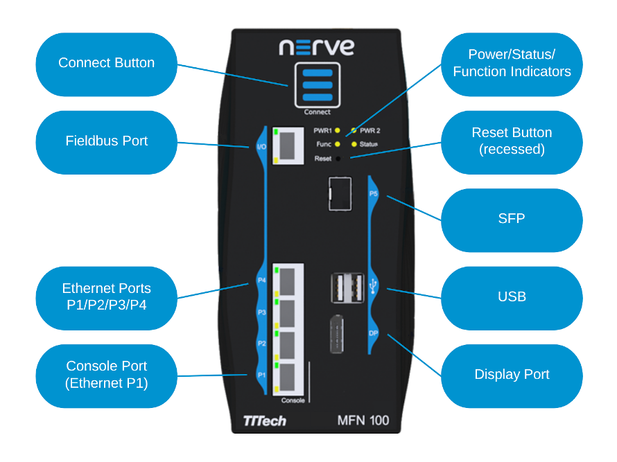
Front panel controls and indicators
Below is an overview of the front panel of the MFN 100, describing physical interfaces, indicators and their labels.
| Label | Description |
|---|---|
| Connect Button | The connect button interrupts the connection on ports P2 to P5 of the MFN 100. This is the behavior in the standard configuration. The function is configurable on request. The button may be configured to change the network configuration. |
| Connection Indicator | The connection indicator is the first fin in the MFN 100 housing. It lights up blue when all required services are initiated and the connection to the Management System is configured. |
| Reset | Holding the button for 4-8 seconds initiates a power cycle. Use a tool with a rounded tip to press the button. |
| Power 1 Power 2 |
Indicators showing power active on the power supply. |
| Status | LED indicating system status
|
| Function | LED indicating CODESYS runtime status
|
| P1 Console | Ethernet port/console port. This port is typically used to connect a workstation to configure the MFN 100. |
| P2/P3/P4 | Ethernet ports |
| P5 | SFP port |
| I/O | Fieldbus interface |
| USB | Two USB 2.0 ports with 1.1 A maximum output current for both ports combined. |
| DP | DisplayPort supporting the DP++ standard. |
Power connectors overview
The power connectors are located at the bottom of the MFN 100 next to the label. There are two separate 24 V inputs, two GND inputs and one Functional Earth (FE) input. The inputs are fused internally. The fuse cannot be replaced by the user. The power supply inputs are protected against reverse polarity.
| Pin | Description |
|---|---|
| 1 | Power supply line 2 |
| 2 | GND |
| 3 | GND |
| 4 | Power supply line 1 |
| 5 | Functional Earth (FE) |
Note
The GND and FE pins (pins 2, 3, and 5) are electrically connected to the housing.
Power supply details
| Parameter | Value |
|---|---|
| Operating voltage | 18 - 30 VDC |
| Start-up current | 7 A max. |
| Consumption | 1.4 A continuous 2.1 A peak |
| Dissipated power | 33.6 W at 24 VDC |
Installation and removal on a DIN rail
The MFN 100 is intended for mounting on a DIN rail inside a closed cabinet. Due to its weight it should be installed on a strong DIN rail. No tool is required to install or remove the MFN 100.
Follow these steps to install the MFN 100 on a DIN rail:
- Engage the DIN rail mounting clip of the MFN 100 with the upper edge of the DIN rail.
- Push the MFN 100 down into the DIN rail.
- Place the MFN 100 in a vertical position so that the mounting clip engages the lower edge of the DIN rail.
Follow these steps to remove the MFN 100 from a DIN rail:
- Push the MFN 100 down.
- Rotate the MFN 100 upwards so that the lower edge of the DIN rail disengages.
- Lift the MFN 100 slightly to remove it.
Setting up the MFN 100
When delivered, Nerve Blue is already installed on the MFN 100. Two network cables and a +24 V DC power supply are required to finish the setup and use Nerve Blue on the MFN 100. This includes connecting the power supply to the mating connector which is delivered with the MFN 100.
- Connect pin 1 of the mating connector to +24 V DC.
- Connect pin 2 of the mating connector to GND.
- Plug the mating connector into the bottom side of the MFN 100.
-
Connect port 2 of the MFN 100 to a DHCP-enabled network.
Note
Port 2 is used for communication with the Management System. Make sure to connect the MFN 100 to the correct network, depending on whether the Management System is hosted on premise or by TTTech Industrial.
-
Plug in the power supply.
The MFN 100 will start after a few minutes and light up blue when all necessary services are initiated.
Note
- Contact the IT administrator for help on how to allow external devices to connect to the network.
- To connect the MFN 100 to a fieldbus, connect a network cable to the I/O port of the MFN 100 and to a fieldbus interface.
- A second power supply can also be connected to the MFN 100 as a backup. To do so, connect pin 3 of the mating connector to GND and connect pin 4 of the mating connector to +24 V DC.
Activating the Nerve Blue license
The product license needs to be activated so that Nerve Blue can be used on the device. Connect a workstation to port P1 and configure the network adapter of the workstation. The IP address has to be in the range from 172.20.2.5 to 172.20.2.254 with a 255.255.255.0 subnet mask.
Access the license activation UI at http://172.20.2.1:3333/ and refer to License activation in the user guide for more information.
Accessing the Local UI and registering the device
With the license activated, the node needs to be registered for use in the Management System through the Local UI. To access the Local UI, first connect a workstation to port P1 and configure the network adapter of the workstation. The IP address has to be in the range from 172.20.2.5 to 172.20.2.254 with a 255.255.255.0 subnet mask. The credentials for the Local UI found in the customer profile are also required.
- Follow this link to connect to the Local UI: http://172.20.2.1:3333/
-
Log in with the credentials from the customer profile.

Continue with Node configuration for information on how to start registering the device in the Management System.
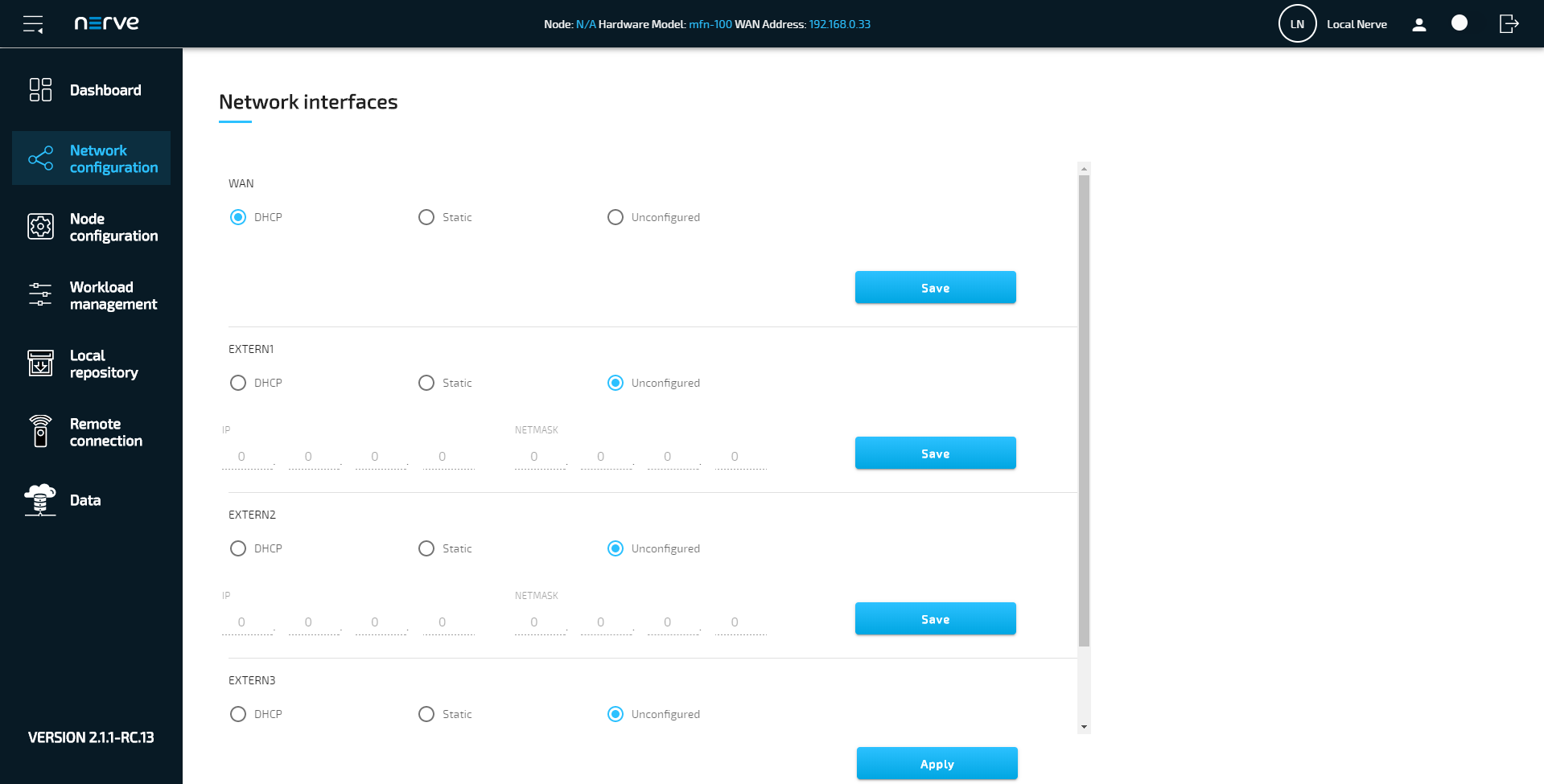
Network configuration
The Ethernet ports of the Nerve Devices can be configured from the Local UI. For the MFN 100, the interfaces in the Local UI represent the physical ports 2, 3, 4 and 5. The console port P1 and the I/O port of the MFN 100 are reserved and cannot be modified. The console port is used solely for configuration purposes. The I/O port is connected to the CODESYS runtime and used for fieldbus communication. Select Network configuration in the navigation on the left to reach this menu.
CODESYS related information
For working with the CODESYS Development System, a device description for Nerve Devices is required. The device description can be downloaded from the Nerve Software Center.
The MFN 100 has an Ethernet port that is reserved for machine data acquisition. Connect a network cable to the I/O port of the MFN 100 and to a fieldbus interface to acquire machine data. The CODESYS runtime can be reached at 172.20.2.2.
Physical ports and network interfaces
Below is a depiction of the node internal networking for the MFN 100. Refer to Node internal networking for more information. The table offers a quick overview of the network interfaces that can be reached through the physical ports of the MFN 100.
| Physical port | Network name |
|---|---|
| I/O | io0 |
| P1 | mgmt |
| P2 | wan |
| P3 | extern1 |
| P4 | extern2 |
| P5 | extern3 |
Below is a graphic that details the available interfaces of the MFN 100 for use with Nerve Blue. Pictured is how the physical interfaces translate to the Host and the CODESYS runtime.
The image shows an example node and how the physical interfaces translate to the Host and the CODESYS runtime. The node consists of the host/domain-0 and the real-time VM running the CODESYS runtime (labeled rtvm). It also has one Virtual Machine workload and two Docker workloads deployed. The virtual machine is located outside of the host and the Docker containers are located in the Docker network inside of the host. However, the workloads are not yet connected.
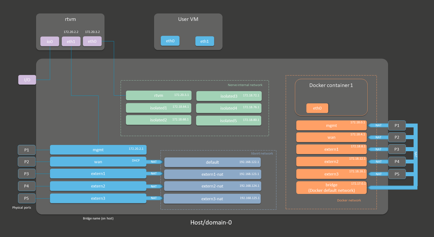
| Notable IP Adresses | |
|---|---|
| Host access | 172.20.2.1 |
| CODESYS runtime access | 172.20.2.2 |
Refer to Node internal networking for more information on networking in the Nerve Blue system.
Updating Nerve Blue from version 2.0 to 2.1
As updating nodes to newer versions through the Management System is a feature introduced in version 2.1, updates from version 2.0 to version 2.1 have to be performed manually. However, before updating the node, contact the sales representative or customer support for information on how to backup current data.
Requirements for updating Nerve Blue on the MFN 100:
|
In addition, a workstation is required to prepare the bootable USB drive. Connect the monitor and the keyboard to the MFN 100.
Before beginning with the installation, make sure that the device will boot from the USB drive. Press F7 when the device is booting to enter the boot menu.
On Windows
- Download the
Nerve_Blue_USB-installer_2.2.1_for_mfn-100.img.tar.gzfrom the Nerve Software Center to a workstation. - Extract the
Nerve_Blue_USB-installer_2.2.1_for_mfn-100.img.tar.gzfile to retrieve theNerve_Blue_USB-installer_2.2.1_for_mfn-100.img. Depending on the program used, the file might need to be extracted more than once. - Transfer the extracted
Nerve_Blue_USB-installer_2.2.1_for_mfn-100.imgfile to the USB drive using Rufus. - Plug the USB drive into a USB port of the Nerve Device.
- Power on the device.
- Press F7 to enter the boot menu. Make sure that the device will boot from the USB drive.
The setup will start automatically and take a few minutes to complete. Select OK when the installation is complete and remove the USB drive. The device will reboot and reach a log in screen, asking for host access log in credentials. Make sure that the device will boot from the hard disk before rebooting the device.
On Linux
- Download the
Nerve_Blue_USB-installer_2.2.1_for_mfn-100.img.tar.gzfile from the Nerve Software Center. -
Enter the following commands to extract the
Nerve_Blue_USB-installer_2.2.1_for_mfn-100.img.tar.gzfile and transfer the extracted file to the USB drive:tar xf Nerve_Blue_USB-installer_2.2.1_for_mfn-100.img.tar.gz sudo dd if=Nerve_Blue_USB-installer_2.2.1_for_mfn-100.img bs=4M of=/dev/sd<drivename> status=progress sync
Note
Make sure to replace
<drivename>with the system name of the USB drive. -
Plug the USB drive into a USB port of the Nerve Device.
- Make sure that the device will boot from the USB drive and power on the device.
The setup will start automatically and take a few minutes to complete. Select OK when the installation is complete and remove the USB drive. The device will reboot and reach a log in screen, asking for host access log in credentials. Make sure that the device will boot from the hard disk before rebooting the device.