Nerve Data Services Gateway
The Gateway is the central application of the Data Services. Its purpose is receiving data from a source via a certain protocol on an input interface and forwarding it to a destination using a different protocol on an output interface. This behavior is reflected in the user configuration as well. In general, the configuration file consists of inputs, outputs and connections between them:
- Inputs are collection interfaces where data is received.
- Outputs are providing interfaces where data can be received from.
- Connections are logical links between inputs and outputs.
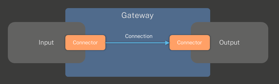
Each input and output provides connectors where a connection can be attached to. A connector is a subset of the data available at an input. This subset is forwarded to the connector of an output where it is distributed further to the data receiver. On an abstract level, this concept is illustrated in the figure below.
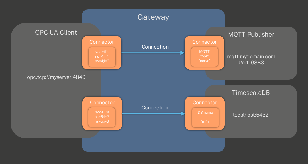
Inputs and outputs hold general configuration data for the protocol they implement. This can be a URL to a server, a port number or something related to timing. A connector of an input or output holds more specific information on how to get or where to send data, for example the node IDs of an OPC UA Server an OPC UA Client input connects to, or the name of a topic for an MQTT Publisher. Each input and output can provide multiple connectors at a time. Data from an input connector can also be connected to multiple output connectors at the same time to distribute data to multiple data consumers. The figure below shows a more specific example of that concept.
Gateway UI
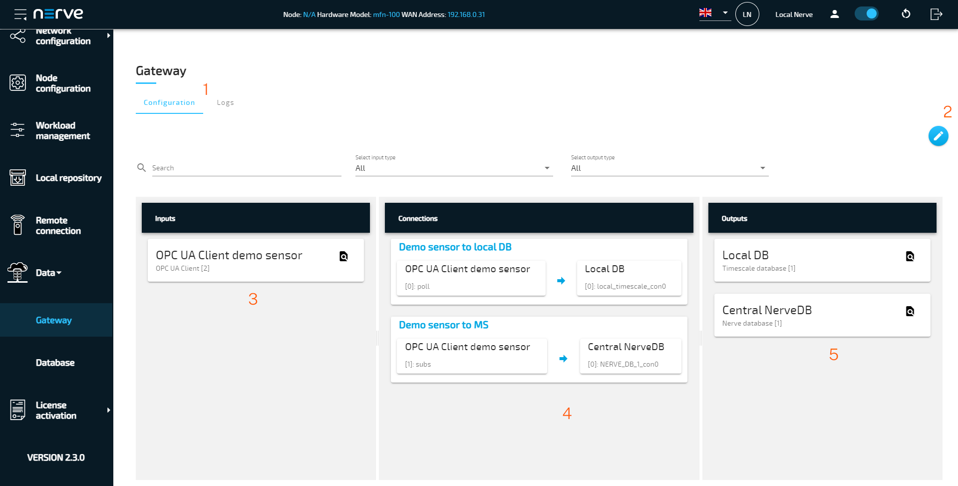
The Gateway UI is the central page of the Data Services and can be reached by selecting Data > Gateway in the navigation on the left in the Local UI. Gateway configurations are applied through the interface in the middle, either through the graphical configuration tool or with a pre-written JSON file that is uploaded. When accessing this page, the panes of the configuration tool displays the last deployed configuration.
| Item | Description |
|---|---|
| Configuration and Logs tabs (1) | The Configuration tab is displayed by default, displaying the graphical configuration tool. The latest logs can be viewed within the Logs tab in the Workload management section of the UI. The entirety of the logs can be exported into a file using the Download button in this tab. |
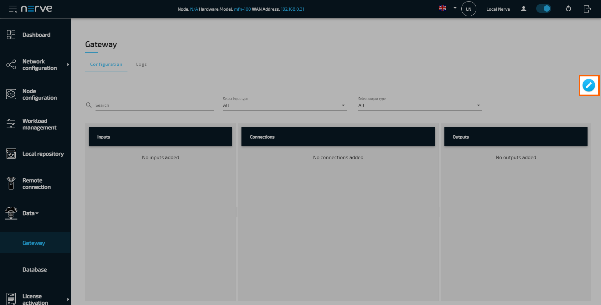
| Edit configuration (2) | Select this button to enable editing mode and enter a configuration into the editor to configure the Gateway. In editing mode, the configuration with the graphical configuration tool is enabled, as well as options to import or export JSON configurations. After selecting the edit button, these buttons appear instead: The following descriptions describe the buttons from left to right.
|
| Inputs (3) | Configured inputs are displayed here. Details can be viewed by selecting the magnifying glass icon. Editing options appear when editing mode is active. |
| Connections (4) | Configured connections are displayed here. Details can be viewed by selecting the magnifying glass icon. Editing options appear when editing mode is active. |
| Outputs (5) | Configured outputs are displayed here. Details can be viewed by selecting the magnifying glass icon. Editing options appear when editing mode is active. |
Applying a configuration to the Gateway
The configuration of the Gateway is applied through the graphical configuration tool in the Gateway section of the Data Services UI. The current configuration of the Gateway is displayed in the separate input, connection and output panes if there is a configuration present in the Gateway. The panes will be empty on initial startup. A new configuration can be entered using the GUI or imported from an existing JSON file. After applying a configuration, check the Logs tab in the Workload management section of the Local UI for any warnings or errors.
The basic structure of the configuration consist of a list of inputs such as an OPC UA server or an MQTT subscriber, outputs such as a Timescale database or an MQTT publisher, and connections between these inputs and outputs. Refer to Gateway configuration parameter descriptions below for the exact syntax. While studying the syntax is required to write a Gateway configuration in JSON format, note that the syntax is also helpful if the graphical configuration tool is used.
Applying a configuration through the GUI
The graphical configuration tool offers a guided way to configure the Gateway. Required fields are marked with a red asterisk. The recommended order is defining an input, defining an output and then defining the connections last.
As a demonstration, the instructions set up a gateway configuration for a simulation sensor providing temperature and humidity data as an OPC UA Server. Temperature data is then stored in the Nerve database at the node. The humidity data is not used in this example.
First, inputs need to be configured. This input will have one connector configured that is required for connecting the database output.
-
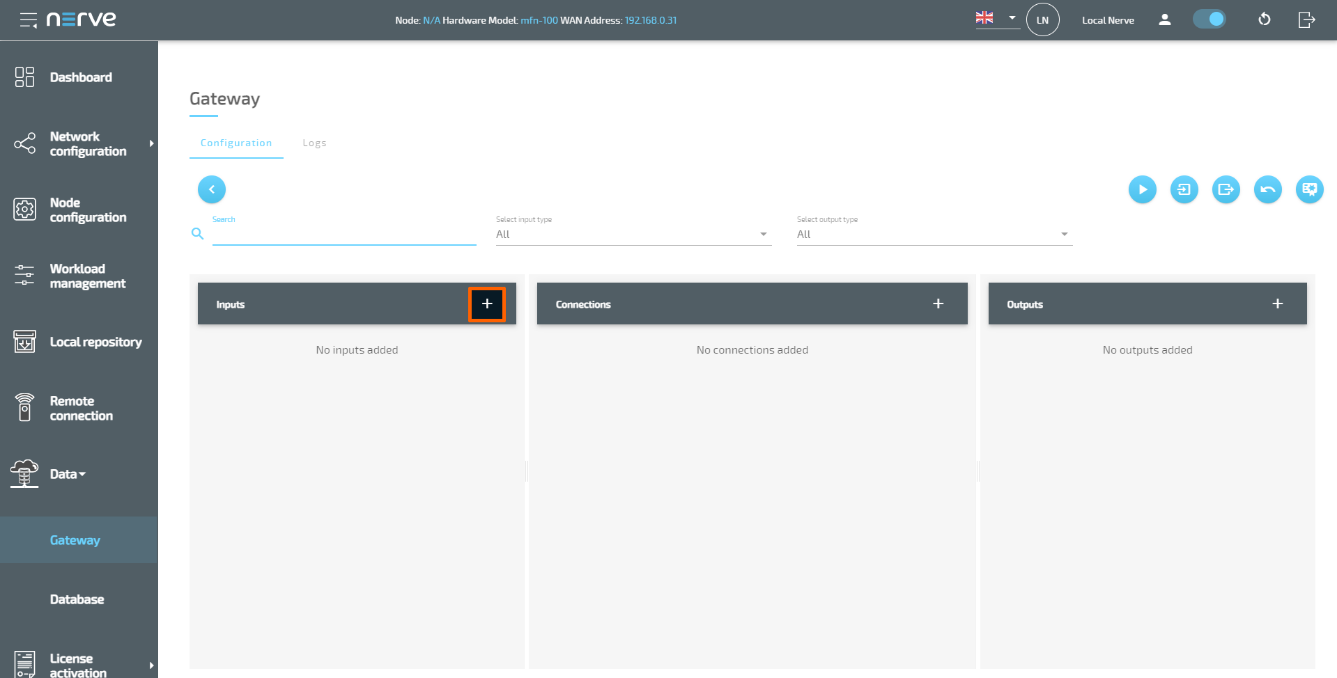
Select the Edit configuration icon on the right.
-
Select the plus icon next to Inputs.
-
Select OPC UA Client from the drop-down menu. A list of parameters will appear.
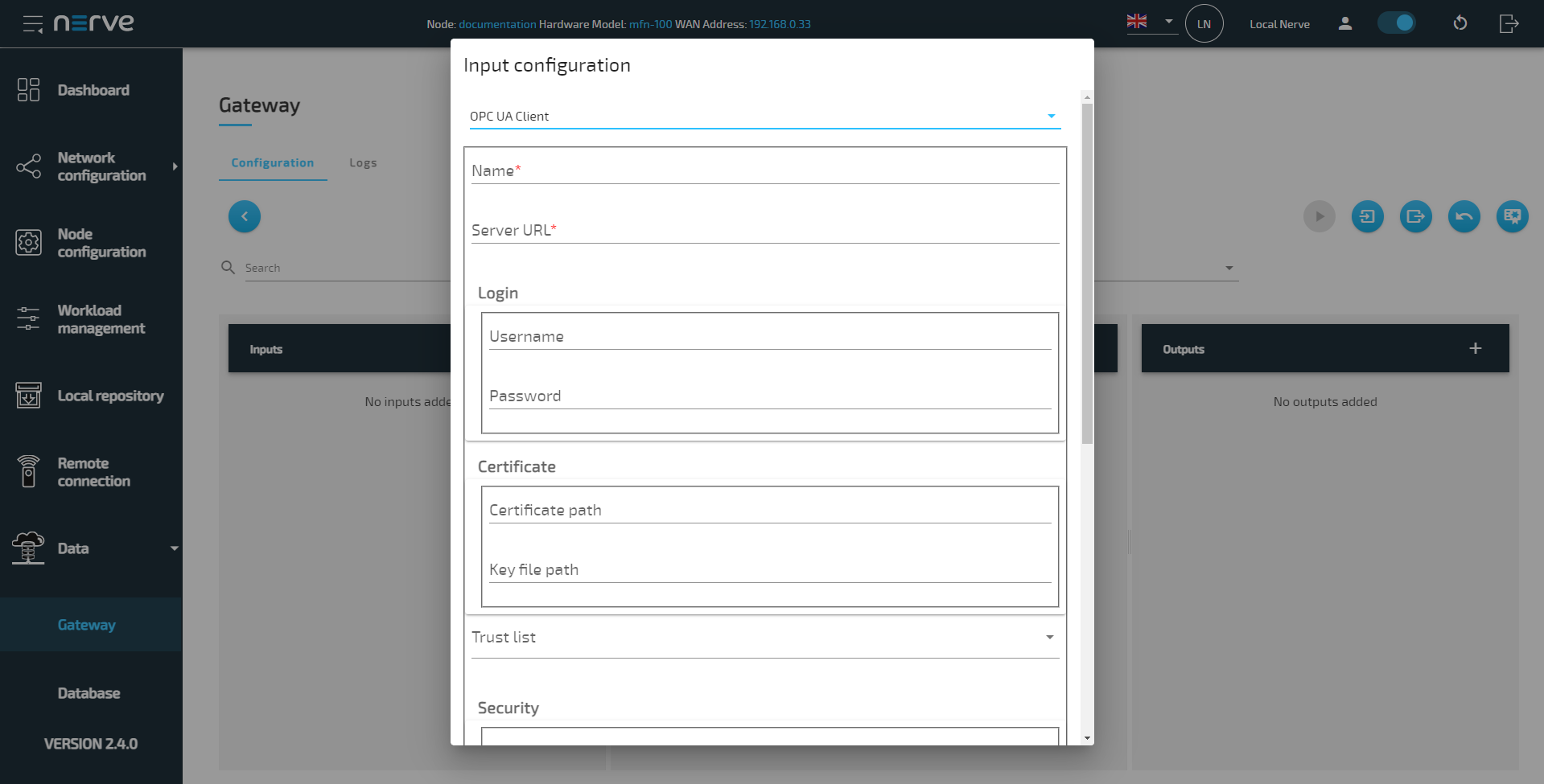
-
Enter the following information:
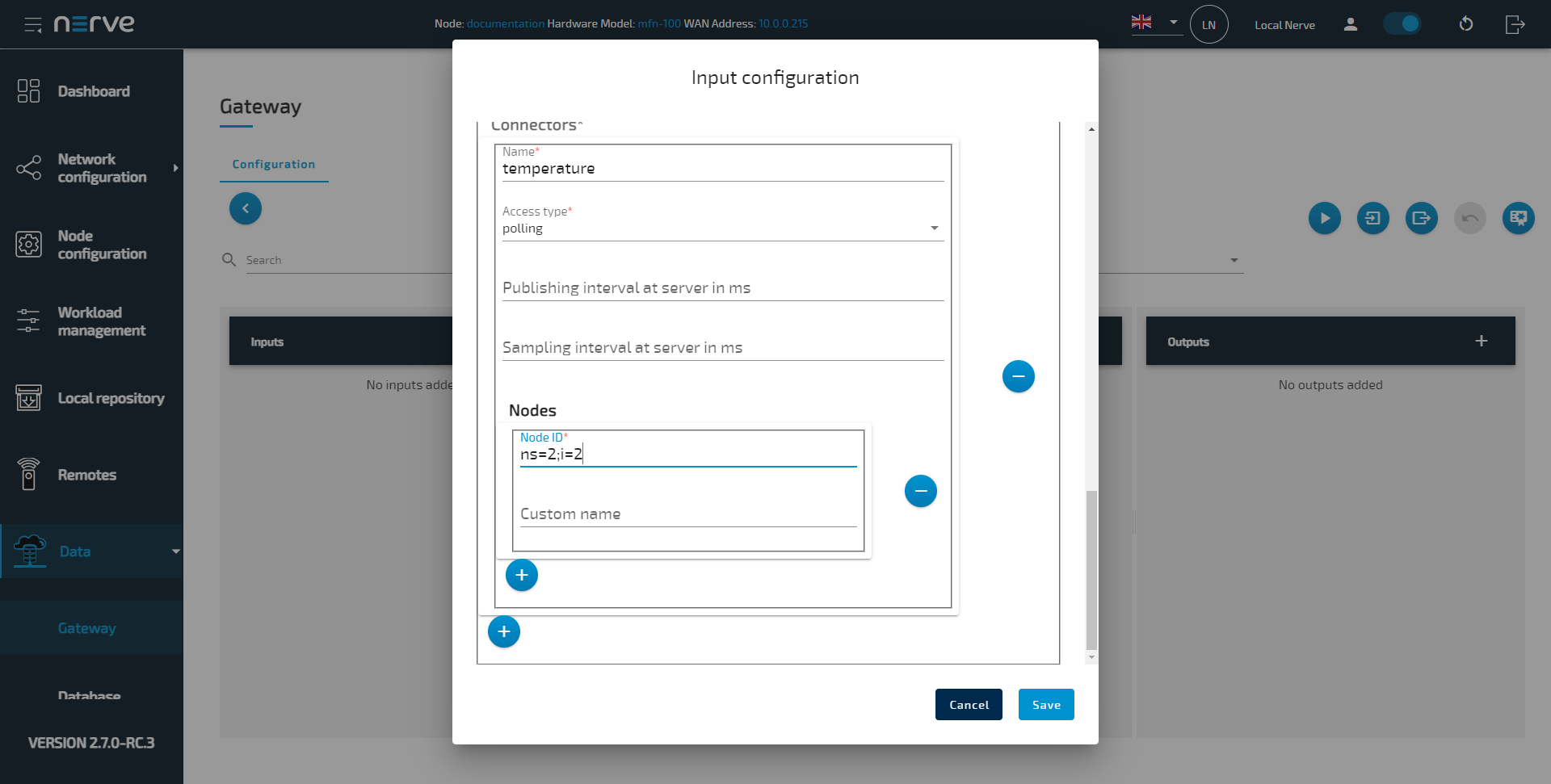
Setting Value Name Enter any name, for example OPC UA Client.Server URL opc.tcp://localhost:4848Polling interval in ms 1000 Connector Select the plus icon and enter the following information:
Name
Enter a name for the connector. This example usestemperature.
Access type
polling
Nodes
Select the plus icon and enter the following information:- Node ID
ns=2;i=2
- Node ID
-
Select Save.
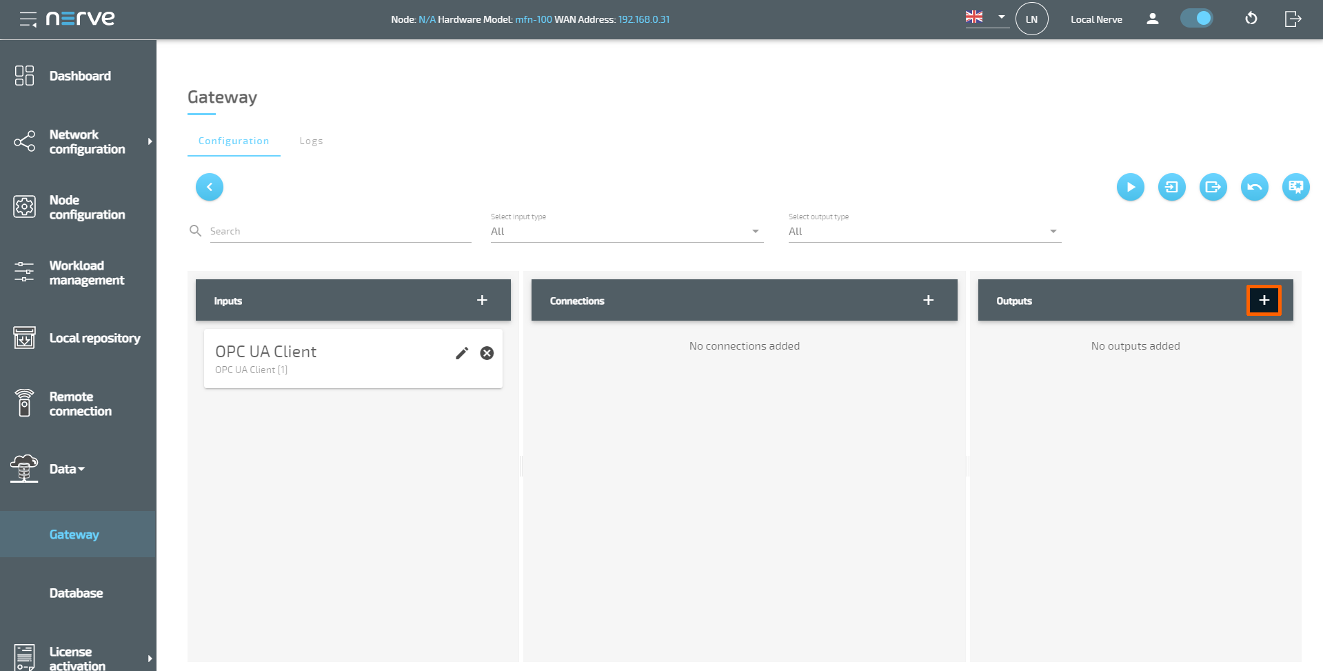
The graphical configuration tool now reflects the configuration above, showing an OPC UA Client input. Next, it is required to define an output before defining connections. A NerveDB output is created for the temperature data of the OPC UA Client input.
-
Select the plus icon next to Outputs.
-
Select Nerve database from the drop-down menu. A list of parameters will appear.
-
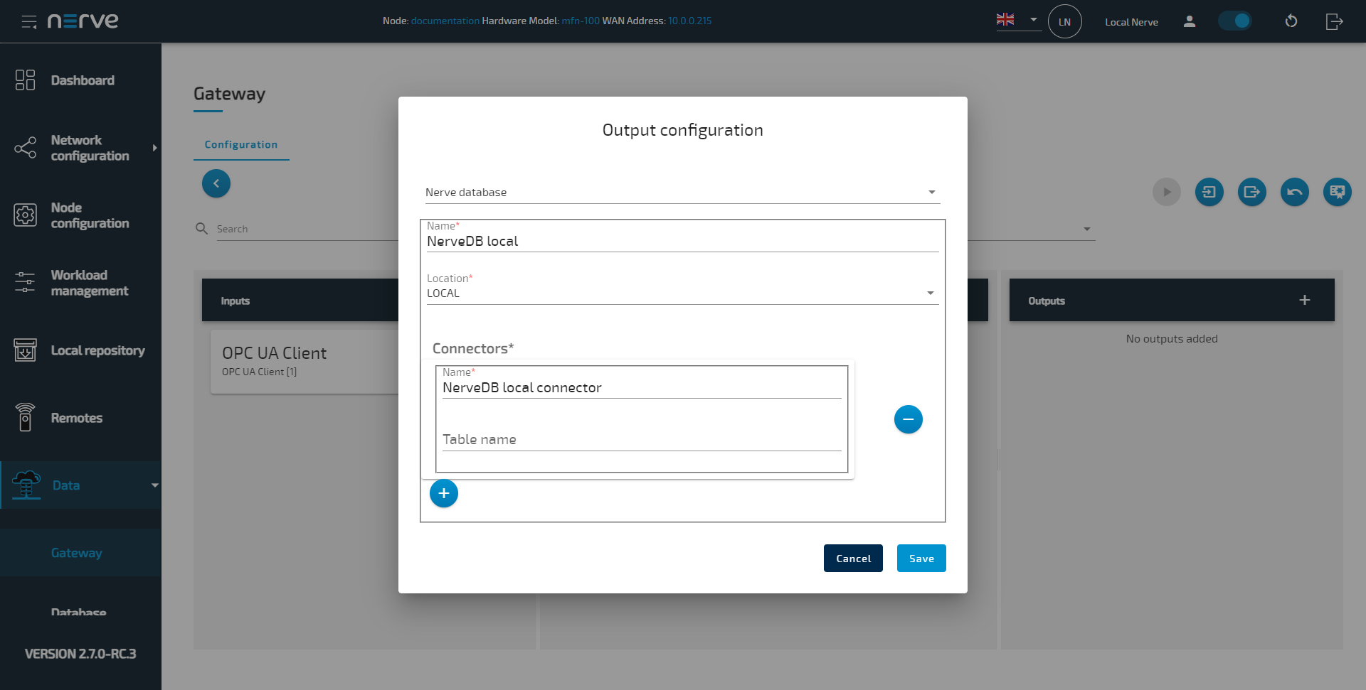
Enter the following information:
Setting Value Name Enter any name, for example NerveDB local.Location LOCALConnector Select the plus icon and enter the following information:
Name
Enter a name for the connector. This example usesNerveDB local connector.
Table name
Enter a name for the data table. If no table name is provided, the name of the connection will be used as a table name. Note that this field is optional when using the local NerveDB. -
Select Save.
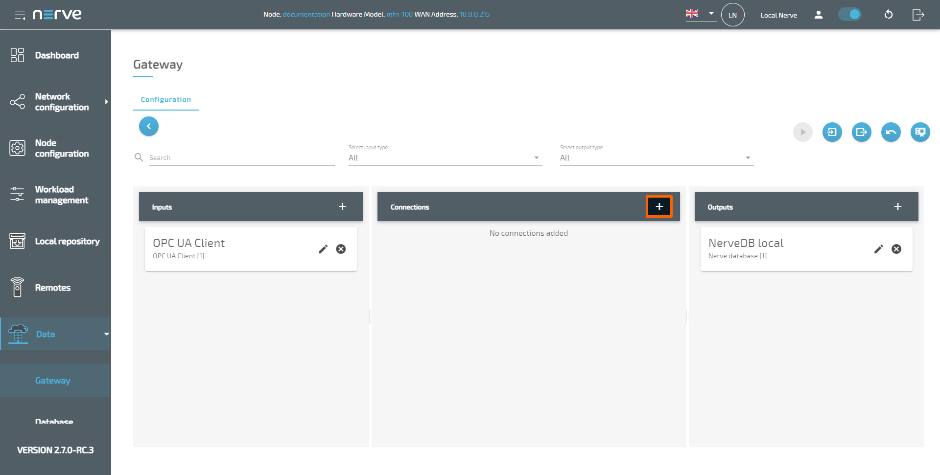
The graphical configuration tool now reflects the configuration above, showing one database output in addition to the OPC UA Client input. With inputs, outputs and their respective connectors defined, connections can now be set up to finalize the Gateway configuration. In this example temperature data is sent to the local NerveDB.
-
Select the plus icon next to Connections.
-
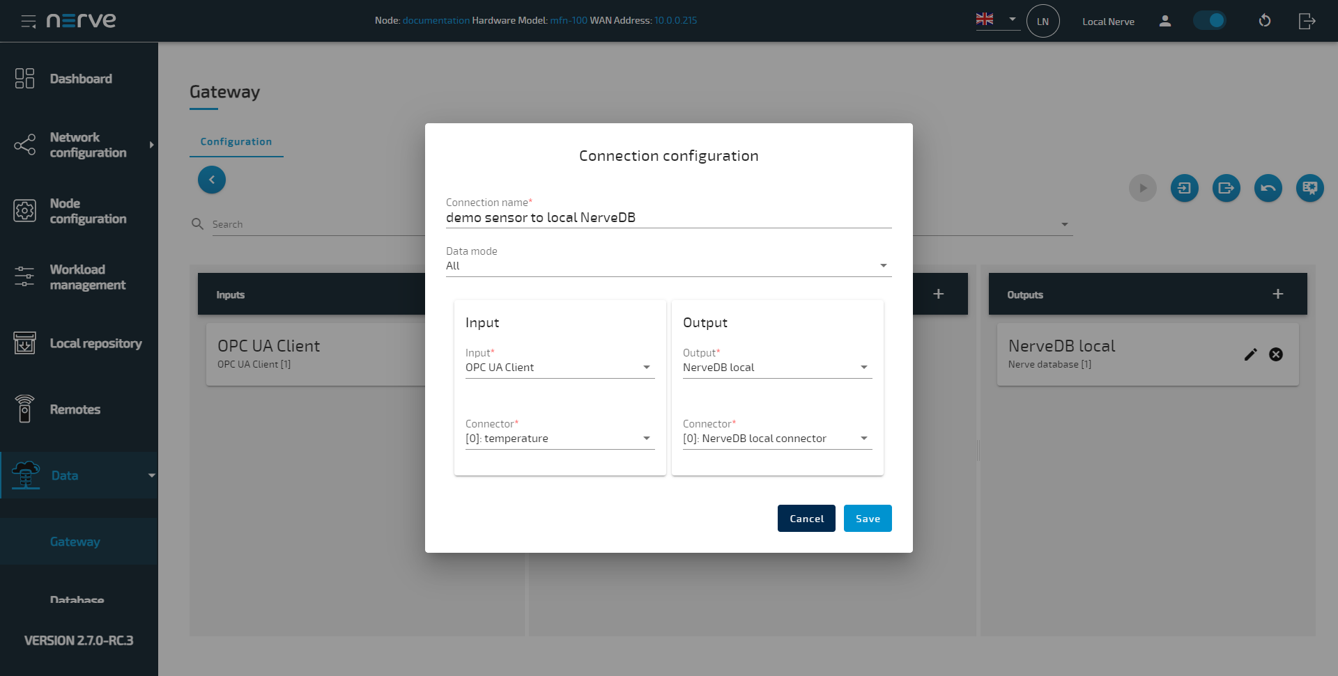
Enter a connection name, for example demo sensor to local NerveDB.
-
Select the following information from the drop-down menus under Input:
Setting Value Input Select the OPC UA Client input, named OPC UA Client in this example. Connector Select the first connector, named [0]: temperature in this example. -
Select the following information from the drop-down menus under Output:
Setting Value Output Select the local NerveDB output, named NerveDB local in this example. Connector Select the connector, named [0]: NerveDB local connector in this example. -
Select Save.
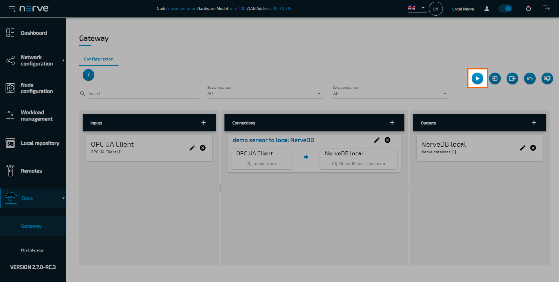
-
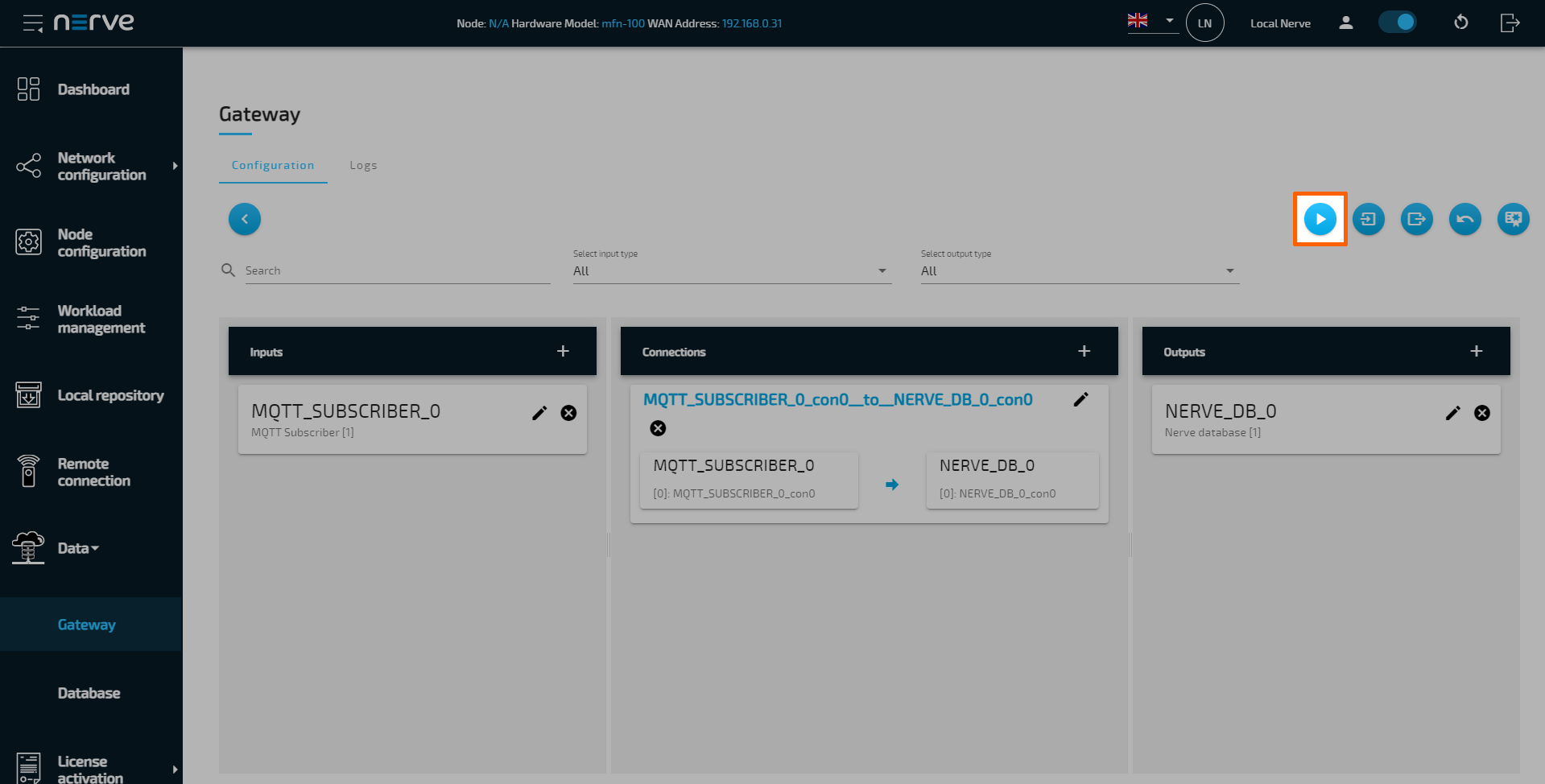
Select the Deploy button. A success message pops up in the upper-right corner.
Note
In case of an already existing configuration, the Gateway might give a warning about which connections will be affected by a short data flow interruption. All other connections will continue to operate and stay unaffected.
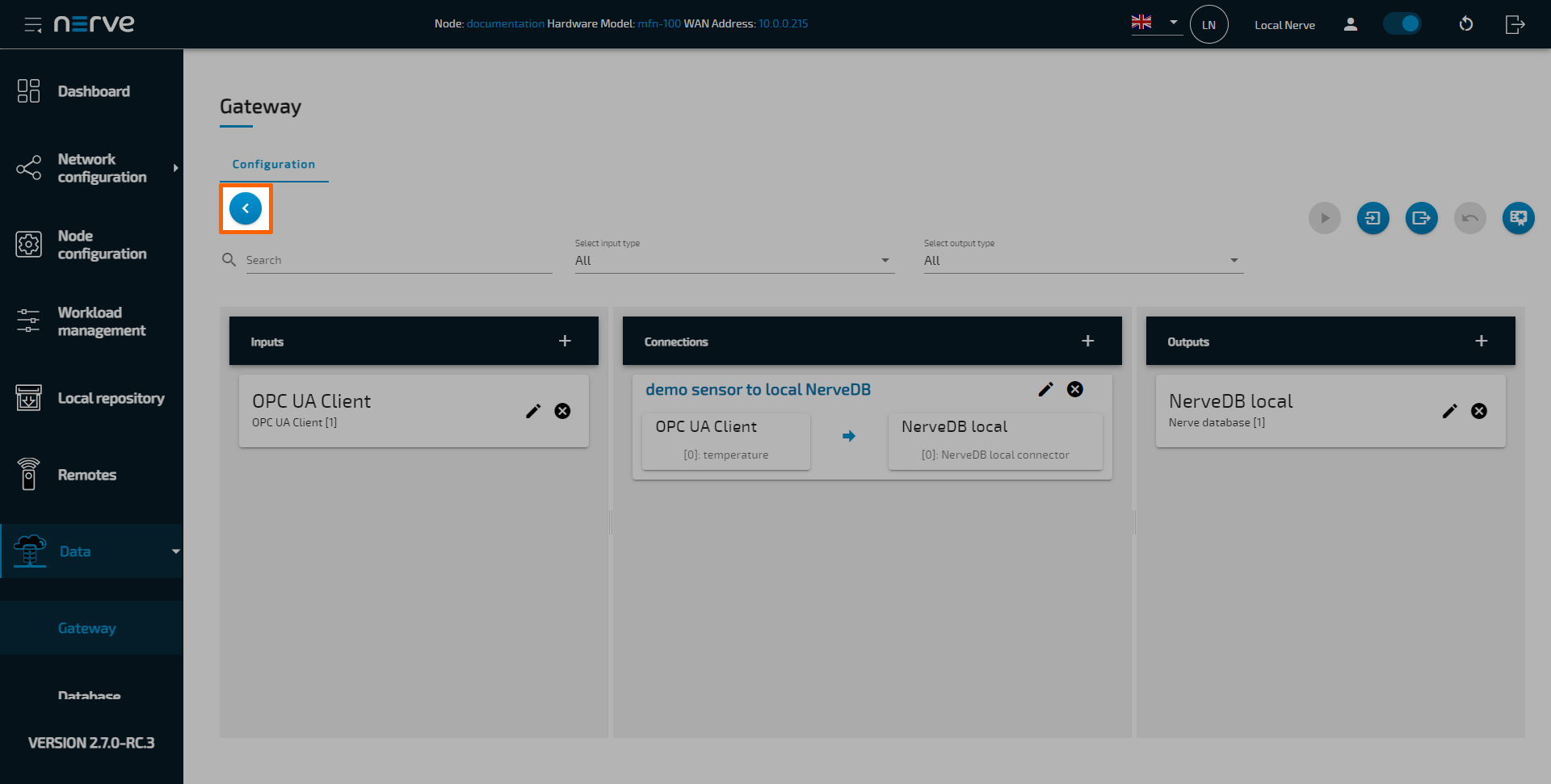
After deploying the configuration, the graphical configuration tool is still in editing mode. Select the arrow on the left side to exit editing mode.
Uploading an existing JSON configuration file
If writing a JSON configuration file is the preferred method of configuring the Gateway, a pre-written JSON file can be uploaded and applied to the Gateway. This method is also useful when following any of the examples in the Examples section.
- Log in to the Local UI.
- Expand Data > Gateway in the navigation on the left.
-
Select the edit button on the right.
-
Select the Import button.
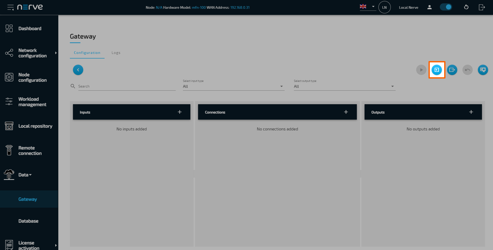
-
Add a pre-written JSON configuration file in the file browser.
-
Select the Deploy button. A success message pops up in the upper-right corner.
The configuration is now deployed. The graphical configuration tool now reflects the settings from the JSON configuration file. Edit the elements in each pane by selecting the edit button in each element. Exit editing mode by selecting the arrow on the left.
For writing JSON configuration files, have a look at the section below and consult the list of parameters for more information on all input, output and connection parameters.
Writing a Gateway configuration file in the Nerve Data Services data format
Inputs and Outputs at the Gateway, using a protocol that does not define a data format (i.e. MQTT), send or receive data in JSON format. As a result, data within the Nerve Data Services is normalized to this format.
The JSON schema below describes the data format in more detail. The JSON schema is also used to validate data upon reception. If a data frame is received that does not comply with the schema, it is silently dropped by the Nerve Data Services.
{
    "$schema": "http://json-schema.org/draft/2019-09/schema#",
    "$id": "https://nerve.cloud/dp/dp_data_model.schema.json",
    "title": "Nerve Data Services JSON data model schema",
    "description": "Schema that represents default data model that Nerve Data Services use.",
    "type": "object",
    "properties": {
        "variables": {
            "type": "object",
            "additionalProperties": {
                "anyOf": [
                    {
                        "type": [ "boolean", "number", "string" ]
                    },
                    {
                        "type": "array",
                        "items": {
                            "type": "boolean"
                        }
                    },
                    {
                        "type": "array",
                        "items": {
                            "type": "number"
                        }
                    },
                    {
                        "type": "array",
                        "items": {
                            "type": "string"
                        }
                    }
                ]
            }
        },
        "timestamp": {
            "type": [ "number", "string", "array" ],
            "items": {
                "type": [ "number", "string" ]
            }
        }
    },
    "required": [ "variables" ],
    "additionalProperties": false
}
The schema defines and allows only two properties in the root object: timestamp and variables. Timestamp is optional, and can be a single value or an array of values. Variables is an object containing arbitrary number of properties, which can be single values or arrays of values.
Custom JSON format
In order to be able to fetch values from all kinds of JSON messages, the Nerve Data Services Gateway supports custom JSON data formats. The value of a field from a JSON message can be fetched using a so-called JSON path. A JSON path is comparable to a file path in a Unix-like file system. As an example, if a file is located in the following file structure:
- Documents
- Personal
- journal.txt
- Personal
its file path would be: /Documents/Personal/journal.txt. Based on this analogy, a JSON field from the following JSON:
{
    "Values": {
        "Temperature": 20
    }
}
would have the following JSON path: .Values.Temperature. Arrays are represented with square brackets:
{
    "Values": {
        "Temperature": [ 20, 30, 40 ]
    }
}
The third value of the Temperature field would be represented the following way: .Values.Temperature[2]
Gateway configuration for custom JSON formats
Note
Custom JSON formats are supported in all inputs using JSON messages.
The fields name and path of the variables array objects inside of the connectors object are used to construct the JSON path. The full JSON path is always constructed by adding name to path:
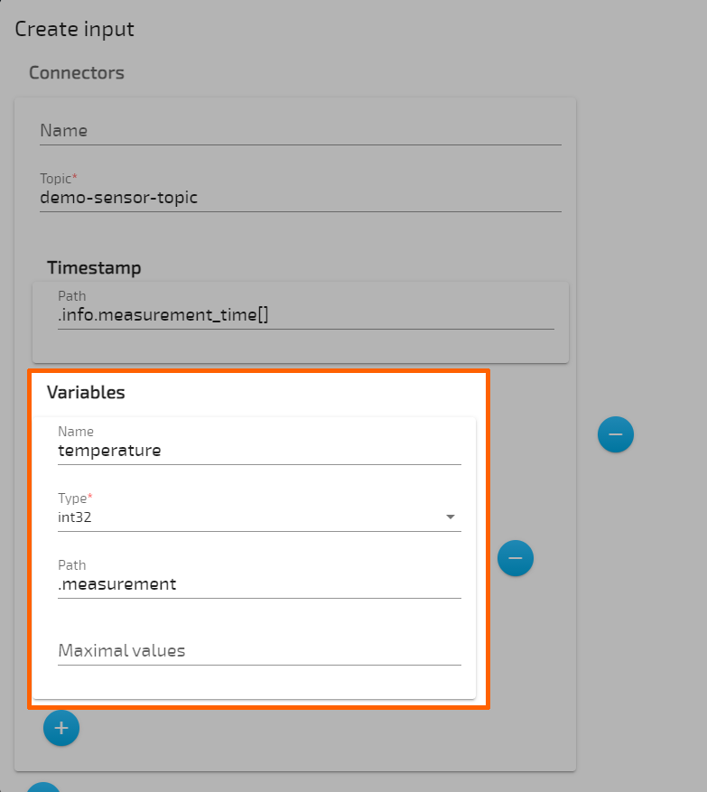
The example above will construct the following JSON path: .measurement.temperature
- The variable name through the rest of the Gateway will always be just the value of the
namefield. (temperaturein the example above). - If
nameis omitted, the value ofpathwill become the name of the variable. - If
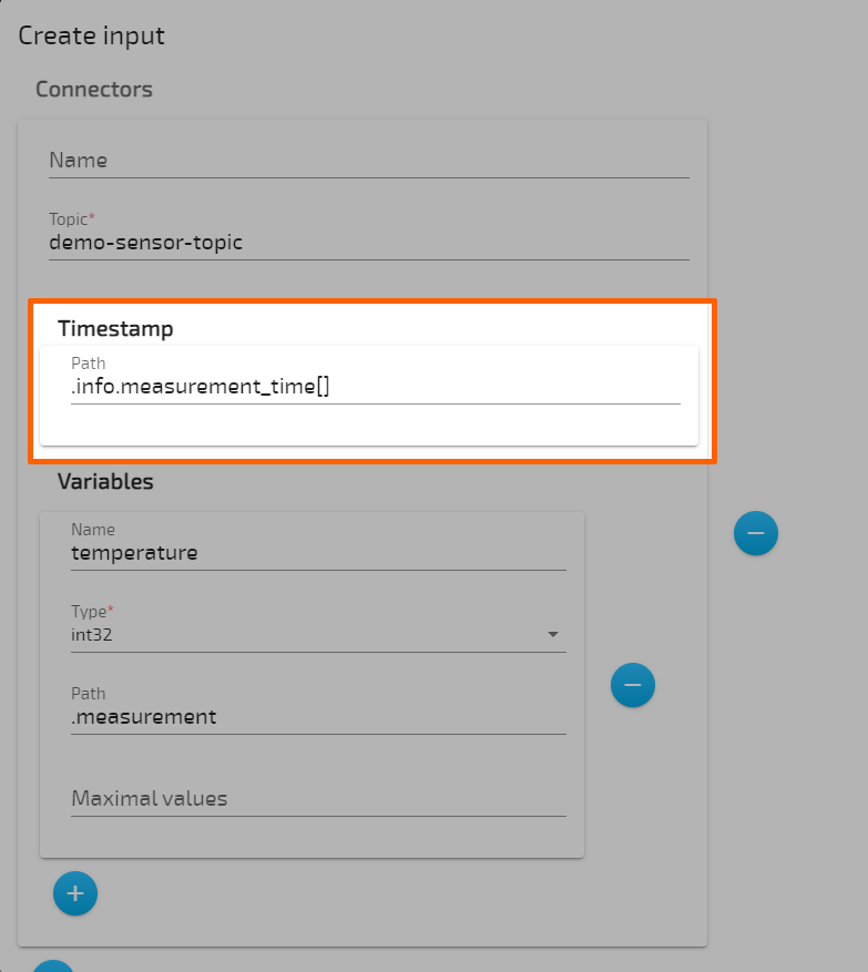
pathis omitted, the value ofpathwill be the default path.variables. This allows the Gateway to use the default Data Services data model JSON schema. - To define a path for timestamps, a special
timestampobject is used in the root of the input. The only field in thetimestampobject ispath, which is used to specify the path where to fetch timestamp values. - This object is optional, and if omitted, the Gateway will look for timestamps under the default JSON path,
.timestamp. This also allows the Gateway to use the default Data Services data model JSON schema.
Timestamp JSON path example
Extended JSON paths
The Gateway extends the JSON paths explained above with an operator for fetching values, in order to reduce the need to write JSON paths for recurring fields. The following data is used for the expansion example below:
{
    "machineB": {
        "sensor1": [
            {
                "temperature": 10,
                "humidity": 51
            },
            {
                "temperature": 20,
                "humidity": 52
            },
            {
                "temperature": 30,
                "humidity": 53
            }
        ]
    }


}
Operator [] - List expansion
The list expansion is an operator used to fetch multiple values of the same variable. It allows processing large chunks of data in a simple way.
The data above, when received with the following configuration:
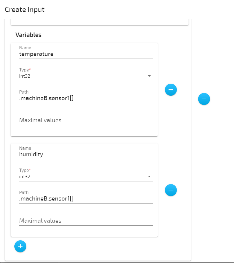
generates 3 entries on any Gateway output.
| temperature | humidity |
|---|---|
| 10 | 51 |
| 20 | 52 |
| 30 | 53 |
Note
The variable expansion operator [*] has been dropped in favor of the native array support available on all JSON inputs and outputs.
Gateway configuration parameter descriptions
The following list gives more information on the parameters that can be set when configuring the Gateway. Parameters are listed by available inputs and outputs in the list below. The description of each parameter also includes information on additional parameters. The following inputs and outputs are included in the list:
| Inputs | Outputs |
|---|---|
| MQTT Subscriber | MQTT Publisher |
| OPC UA PubSub Subscriber | OPC UA PubSub Publisher |
| OPC UA Client | OPC UA Server |
| Modbus Server | ZeroMQ Publisher |
| S7 Server | Azure IoT Hub Device |
| ZeroMQ Subscriber | Kafka Producer |
| Kafka Consumer | NerveDB |
| TimescaleDB | |
| Influx DB |
Inputs
In the graphical configuration tool, mandatory fields are marked with a red asterisk.
OPC UA Client
Note
Do not use a few seconds or fractions of seconds as time values for requestedSessionTimeout and secureChannelLifeTime when configuring an OPC UA Server for the Gateway to connect to. When using those time values, the Gateway's OPC UA Client might not work properly, resulting in a loss of data sent by the server.
| Object | Values and descriptions |
|---|---|
| Name | Enter a name for the input. This name is also used in log messages. |
| Server URL | Enter the URL of the server the input will connect to, i.e. opc.tcp://myserver.com:4840. This requires an OPC UA Server source to be configured.As an example, use opc.tcp://172.20.2.2:4840 to connect the Gateway to CODESYS. |
| Login | Enter Username and Password of the source OPC UA Server if authentication parameters have been defined. |
| Certificate | Enter the file names of the certificate under Certificate path and key file under Key file path for client authentication. This requires a certificate and key file to be uploaded through the Import certificates button in the Gateway's edit mode. Certificates must be in DER format. Example: certificate.der or keyfile.der |
| Trust list | Enter the certificate file names of trusted OPC UA Servers here. With added certificates here, the Gateway will only connect to OPC UA Servers presenting these certificates. Note that this requires the certificates to be uploaded through the Import certificates button in the Gateway's edit mode. Certificates must be in DER format. Example: server_a_cert.der, server_b_cert.der, server_c_cert.der |
| Security | Choose the security mode and policy for the connection. The security mode defines if messages have to be cryptographically signed, or encrypted as well. The security policy determines the cryptographic algorithm used to sign and encrypt messages. Security mode Choices are None, Sign, SignAndEncrypt.Security policy Choices are None, Basic128Rsa15, Basic256 and Basic256Sha256.Note that the following warning appears in the Gateway when using an OPC UA Client input with security settings: WARNING: INTERNAL opcua_client: The configured ApplicationURI does not match the URI specified in the certificate for the SecurityPolicy http://opcfoundation.org/UA/SecurityPolicy#NoneThis is expected due to the OPC UA library the Gateway is based on. |
| Description | This is the description of the OPC UA Client. Application URI The application URI of the client is the globally unique identifier for the application instance, used in the secure connection certificate. If a certificate has been added earlier, this field must match the URI in the certificate. Example: urn:myfactory.com:Machine54:UA ServerApplication Name This is the OPC UA Client's string representation for a server. An OPC UA application delivers this when information on the client is requested. The default value will be used if this field is left empty. The default value of the Gateway OPC UA Client is Nerve Data Services - Gateway OPC UA Client. |
| Force session to be kept alive | Tick this checkbox in order to force the server to keep the session alive by constantly polling an arbitrary server value. Some OPC UA servers have been observed having problems keeping the session alive. |
| Enable server rebrowsing to detect changes in the address space | Tick this checkbox to enable periodical rebrowsing in order to detect changes in the address space of the server. When the checkbox is ticked, a new field labeled Rebrowsing interval in hours is added. Specify the size of the interval in hours. Decimal values are possible, e.g. 0.5. The default setting is 1. |
| Polling interval in ms | This is the interval at which the Gateway polls values from the server in milliseconds. This setting is in effect when the polling access type is used. |
| Include object path in variable name | Tick this checkbox to enable the full path in the variable name. This includes names of parent nodes separated by .. When the object is browsed, all information of the parent node is available. Therefore, the entire path can be added to the variable name. When browsing the node that represents variables though, there is only information of that given node. In this case, there is no information for including the path of the parent object and only the variable name will be read. |
| Connectors | Select the plus icon to add a connector. Note that adding a connector is required for establishing a connection between inputs and outputs. Add another connector by selecting the plus icon at the end of the Connectors field that opened. Name Enter a name for the connector. This makes the connector easy to identify when defining connections. Access type This is the access mode of the Gateway OPC UA Client. Options are polling and subscription.
Define the interval at which the server is publishing values in milliseconds. The publishing interval determines the interval at which the OPC UA server sends notification of changes in the values of variables, if there are any, to the Gateway OPC UA Client. Sampling interval at server in ms Define the sampling interval at which the server updates its values in milliseconds. The sampling interval determines the interval at which the OPC UA server internally checks the values of variables for changes that have occurred. Nodes Select the plus icon to add variable nodes:
To enable filtering of the node ID string, add the identifier r with a regex string in the format r=<regexstring>. Example: ns=1;r=.*VariablesObjects. The regex expression is used to match object nodes on the server.Note that this option is a Nerve Data Services feature and is not part of the OPC UA standard. Supported data types Note that the Gateway supports the structure data type for the OPC UA Client input. Structure support allows the handling of complex objects that are composed of other data types. Specifically, the Gateway can handle
Also note that to work with the Gateway, structures in the OPC UA Server need to be configured according to https://reference.opcfoundation.org/PLCopen/v102/docs/9.2.3.4. Therefore it is necessary that:
Boolean, SByte, Byte, Int16, UInt16, Int32, UInt32, Int64, UInt64, Float, Double, String, DateTime, GUID and ByteString. For more information about OPC UA Client and the structure data type, refer to the official OPC UA documentation. |
MQTT Subscriber
| Object | Values and descriptions |
|---|---|
| Name | Enter a name for the input. This name is also used in log messages. |
| Client ID | Client ID of the MQTT_SUBSCRIBER. |
| Server URL | Protocol and URL of the server to connect to, i.e. tcp://myserver.com:4840. Possible protocols are: tcp, mqtt, mqtts, ssl, ws or wss. When omitted, tcp is used by default. |
| Username | Enter the username for the MQTT broker. |
| Password | Enter the password for the MQTT broker. |
| Keep alive interval | Define the maximum time allowed of no communication between client and server in seconds. |
| Clean session | Tick this checkbox to define whether the server should remember the state of the client after reconnecting. |
| QOS | Quality of Service value. Possible values are 0, 1 or 2. |
| SSL Options | Secure connection options: CA certificate path Path to CA certificate file. Certificate path Path to certificate file. Key file path Path to key file. Key password Password for the given key. Server authentication required Tick this checkbox to activate server authentication. |
| Connectors | Select the plus icon to add a connector. Note that adding a connector is required for establishing a connection between inputs and outputs. Add another connector by selecting the plus icon at the end of the Connectors field that opened. Array of connectors for the MQTT_SUBSCRIBER: Name Enter a name for the connector. This makes the connector easy to identify when defining connections. Topic Enter the name of the MQTT topic that was defined in the MQTT Publisher. Timestamp Timestamp related options
Array of variables expected to be received:
|
ZeroMQ Subscriber
| Object | Values and descriptions |
|---|---|
| type | Type of input (ZEROMQ_SUBSCRIBER). |
| Name | Name of the ZEROMQ_SUBSCRIBER input used in log messages. |
| serverUrls | Array of server URLs for this subscriber instance to connect to, i.e. [tcp://myserver:5555, tcp://myserver:5556]. |
| Connectors | Array of connectors for ZEROMQ_SUBSCRIBER: Name Connector name. topic Name of the ZeroMQ topic to use. timestamp Timestamp related options.
Array of variables expected to be received:
|
OPC UA PubSub Subscriber
| Object | Values and descriptions |
|---|---|
| type | Type of input (OPC_UA_PS_SUBSCRIBER). |
| Name | Name of the OPC_UA_PS_SUBSCRIBER input used in log messages. |
| mqttClientId | Client ID of the OPC_UA_PS_SUBSCRIBER when MQTT transport is used. Required when MQTT is used. |
| networkAddressUrl | URL of the OPC UA PubSub connection to subscribe to. |
| networkInterface | Name of the network interface to use. |
| encoding | Type of message encoding (JSON/UADP). |
| Connectors | Array of connectors for the OPC_UA_PS_SUBSCRIBER: Name Connector name. publisherId Publisher ID for the writer group. writerGroupId Writer group ID. dataSetWriterId Data set writer ID. fieldsReversePublished Some publishers send fields within a data set message in a reversed order compared to how the fields were added to that publisher. If this field is set to true, the user can use field indexes in the config file in the same order as the fields were added to these publishers. Must be set to true when connecting to a publisher using the TTTech PubSub library (i.e. CODESYS).mqttTopic Name of the MQTT topic if transport protocol is MQTT, ignored otherwise. Required when MQTT is used. variables Array of variables expected to be received:
|
S7 Client
| Object | Values and descriptions |
|---|---|
| type | Type of output (S7_CLIENT). |
| Name | Name of the S7_CLIENT instance used in log messages. |
| serverUrl | URL of the S7 server to connect to. |
| port | Port at which to connect to. |
| connectionType | Connection type (PG, OP, S7_BASIC). |
| localTsap | Local tsap, mandatory if s7 basic connection type. |
| remoteTsap | Remote tsap, mandatory if s7 basic connection type. |
| pollingInterval_ms | Interval for polling values from server in miliseconds. |
| rack | S7 device rack. |
| slot | S7 device slot. |
| Connectors | Array of connectors for S7_CLIENT: Name Connector name. merkers Array of S7 merkers:
Array of S7 inputs:
Array of S7 outputs:
Array of S7 timers:
Array of S7 counters:
Array of S7 datablocks:
|
Modbus Client
| Object | Values and descriptions |
|---|---|
| type | Type of output (MODBUS_CLIENT). |
| Name | Name of the MODBUS_CLIENT instance used in log messages. |
| serverUrl | URL of the Modbus server to connect to. |
| port | Port at which to connect to. |
| pollingInterval_ms | Interval at which to poll values from the server in milliseconds. |
| Connectors | Array of connectors for the MODBUS_CLIENT: Name Connector name. coils Array of Modbus coil type:
Array of Modbus discrete input type:
Array of Modbus input register type:
Array of Modbus holding register type:
|
Kafka Consumer
| Object | Values and description |
|---|---|
| type | Type of input (KAFKA_CONSUMER). |
| name | Name of the KAFKA_CONSUMER instance used in log messages. |
| bootstrapServers | Array of bootstrap servers URLs. |
| clientId | Client ID to use for the Kafka client. |
| groupId | ID of the group to which this consumer will join. |
| securityProtocol | Security protocol to use when connecting to the Kafka broker. |
| sslOptions | Object describing SSL options. Only relevant if securityProtocol is SSL. sslCertificateLocation Location of the certificate. sslKeyLocation Location of the certificate key. sslKeyPassword Key password. sslCaLocation CA certificate location. sslCrlLocation CRL location. sslKeyStoreLocation Location of the key store directory. sslKeyStorePassword Key store password. |
| connectors | Array of connectors for the KAFKA_CONSUMER: name Connector name. topic Name of the Kafka topic to use. timestamp Timestamp related options.
Array of variables expected to be received:
|
Outputs
In the graphical configuration tool, mandatory fields are marked with a red asterisk.
TimescaleDB
| Object | Values and descriptions |
|---|---|
| type | Type of output (DB_TIMESCALE). |
| Name | Name of the DB_TIMESCALE instance used in log messages. |
| url | URL of the TimescaleDB server to connect to. |
| port | Port at which to connect to. |
| dataRate_MBps | Hypertable data rate in MegaBytes per second. |
| chunkTimeInterval_s | Hypertable chunk time interval in seconds. |
| connectors | Array of connectors for DB_TIMESCALE: Name Connector name. dbName Database name to connect to. tableName Table name to write into. user Username for authentication. password Password for authentication. booleanAsSmallint Whether boolean should be represented as PostgreSQL small int data type. |
InfluxDB
| Object | Values and descriptions |
|---|---|
| type | Type of output (DB_INFLUX). |
| Name | Name of the DB_INFLUX instance used in log messages. |
| url | URL of the InfluxDB server to connect to. |
| port | Port at which to connect to. |
| Connectors | Array of connectors for DB_INFLUX: Name Connector name. dbName Database name to connect to. user Username for authentication. password Password for authentication. |
MQTT Publisher
| Object | Values and descriptions |
|---|---|
| Name | Name of the MQTT_PUBLISHER instance used in log messages. |
| Client id | Client ID of the MQTT_PUBLISHER. |
| Server URL | Protocol and URL of the server to connect to, i.e. tcp://myserver.com:4840. Possible protocols are: tcp, mqtt, mqtts, ssl, ws or wss. When omitted, tcp is used by default. |
| Username | MQTT broker authentication username. |
| Password | MQTT broker authentication password. |
| Keep alive interval in s | Maximum time allowed of no communication between client and server. |
| Clean session | Defines whether the server should remember state for the client across reconnect. |
| Qos | Quality of Service value (0-2). |
| SSL options | Secure connection options: CA certificate path Path to CA certificate file. Certificate path Path to certificate file. Key file path Path to key file. Key password Password for the given key. Server authentication required Defines whether server authentication is required. |
| Connectors | Array of connectors for MQTT_PUBLISHER: Name Connector name. Topic Name of the MQTT topic to use. Timestamp required Defines whether a timestamp is added to each message or not. Timestamp format Format of the timestamp in a message, either iso (ISO 8601) or unix_ns (UNIX time in nanoseconds since Jan 01 1970 (UTC)).Max list size Maximum array size of variables, if sent as arrays. If size is larger than the max data will be sent in chunks of Max list size. Timestamp Timestamp options:
Array of variables for which a custom JSON path is desired:
|
OPC UA PubSub Publisher
| Object | Values and descriptions |
|---|---|
| type | Type of output (OPC_UA_PS_PUBLISHER). |
| Name | Name of OPC_UA_PS_PUBLISHER instance used in log messages. |
| networkAddressUrl | URL of the OPC UA PubSub connection to publish to. |
| networkInterface | Name of the network interface to use. |
| encoding | Type of message encoding (JSON/UADP). |
| Connectors | Array of connectors for OPC_UA_PS_PUBLISHER: Name Connector name. publisherId Publisher ID of OPC UA PubSub connection. writerGroupId Writer group ID in the OPC UA PubSub connection. dataSetWriterId Data set writer ID in the writer group. publishInterval_ms Interval at which publisher publishes messages. keyFrameCount Key frame count for messages. mqttTopic Topic to publish to in case of MQTT connection. mqttClientId MQTT client ID for PubSub connection in case of MQTT connection. This must be unique for each connector. Required when MQTT is used. |
OPC UA Server
| Object | Values and descriptions |
|---|---|
| type | Type of output (OPC_UA_SERVER). |
| Name | Name of OPC_UA_SERVER instance used in log messages. |
| customHostname | Custom hostname of the server, used for discovery URL. |
| port | Port to listen at (defaults to 4840). |
| logins | Array of username/password pairs available for authentication: username Username for authentication. password Password for authentication. |
| securities | Array of available security modes and policies: securityMode Security Mode ("all" keyword is supported to create all available endpoints for chosen Security Policy). securityPolicy Security Policy ("all" keyword is supported to create all available endpoints for chosen Security Mode). |
| certificate | Server's certificate: certFilePath Path to Server Instance Certificate. keyFilePath Path to private key. |
| description | Server Description: applicationUri Server Application URI. applicationName This is the client's string representation for a server. |
| trustList | Array of trusted certificates. |
| addressSpaceFolders | OPC_UA_SERVER address space tree: browseName OPC UA Folder browse name. displayName OPC UA Folder display name. description OPC UA Folder description. namespaceURI OPC UA Folder namespace URI. identifier OPC UA Folder nodeID identifier. children Array of OPC UA childFolders, same format as addressSpaceFolders field. connectorIndicies Array of indicies of connectors, placed in the OPC UA Folder. |
| Connectors | Array of connectors for OPC_UA_SERVER: Name Connector name. browseName OPC UA node browse name. displayName OPC UA node display name. description OPC UA node description. namespaceURI OPC UA node namespace URI. identifier OPC UA node nodeID identifier. |
OPC UA Client Output
| Object | Values and descriptions |
|---|---|
| Name | Enter a name for the input. This name is also used in log messages. |
| Server URL | Enter the URL of the server the input will connect to, i.e. opc.tcp://myserver.com:4840. This requires an OPC UA Server source to be configured. |
| Login | Enter Username and Password of the OPC UA Server if authentication parameters have been defined. |
| Certificate | Enter the file names of the certificate under Certificate path and key file under Key file path for client authentication. This requires a certificate and key file to be uploaded through the Import certificates button in the Gateway's edit mode. Certificates must be in DER format. Example: certificate.der or keyfile.der |
| Trust list | Enter the certificate file names of trusted OPC UA Servers here. With added certificates here, the Gateway will only connect to OPC UA Servers presenting these certificates. Note that this requires the certificates to be uploaded through the Import certificates button in the Gateway's edit mode. Certificates must be in DER format. Example: server_a_cert.der, server_b_cert.der, server_c_cert.der |
| Security | Choose the security mode and policy for the connection. The security mode defines if messages have to be cryptographically signed, or encrypted as well. The security policy determines the cryptographic algorithm used to sign and encrypt messages. Security mode Choices are None, Sign, SignAndEncrypt.Security policy Choices are None, Basic128Rsa15, Basic256 and Basic256Sha256.Note that the following warning appears in the Gateway when using an OPC UA Client input with security settings: WARNING: INTERNAL opcua_client: The configured ApplicationURI does not match the URI specified in the certificate for the SecurityPolicy http://opcfoundation.org/UA/SecurityPolicy#NoneThis is expected due to the OPC UA library the Gateway is based on. |
| Description | This is the description of the OPC UA Client. Application URI The application URI of the client is the globally unique identifier for the application instance, used in the secure connection certificate. If a certificate has been added earlier, this field must match the URI in the certificate. Example: urn:myfactory.com:Machine54:UA ServerApplication Name This is the OPC UA Client's string representation for a server. An OPC UA application delivers this when information on the client is requested. The default value will be used if this field is left empty. The default value of the Gateway OPC UA Client is Nerve Data Services - Gateway OPC UA Client. |
| Connectors | Select the plus icon to add a connector. Note that adding a connector is required for establishing a connection between inputs and outputs. Add another connector by selecting the plus icon at the end of the Connectors field that opened. Name Enter a name for the connector. This makes the connector easy to identify when defining connections. Variables Select the plus icon to add variable nodes:
|
ZeroMQ Publisher
| Object | Values and descriptions |
|---|---|
| type | Type of output (ZEROMQ_PUBLISHER). |
| Name | Name of the ZEROMQ_PUBLISHER instance used in log messages. |
| serverUrl | Server endpoint to publish to. Subscribers connect to it. |
| Connectors | Array of connectors for ZEROMQ_PUBLISHER: Name Connector name. topic Name of the ZeroMQ topic to publish to. timestampRequired Defines whether a timestamp is added to each message or not. timestampFormat Format of the timestamp in a message, either iso (ISO 8601) or unix_ns (UNIX time in nanoseconds since Jan 01 1970 (UTC)).maxListSize Maximum array size of variables, if sent as arrays. If size is larger than the max data will be sent in chunks of maxListSize. timestamp Timestamp options:
Array of variables for which a custom JSON path is desired:
|
Azure IoT Hub Device
| Object | Values and descriptions |
|---|---|
| type | Type of output (AZURE_IOT_HUB_DEVICE). |
| Name | Name of the AZURE_IOT_HUB_DEVICE instance used in log messages. |
| deviceConnectionString | Connection string of the device created in the MS Azure IoT Hub. |
| mqttOverWss | Determines if the AZURE_IOT_HUB_DEVICE instance should use MQTT over WSS (port 433) or regular MQTT over TLS/SSL (port 8883) to connect to the Azure IoT Hub broker. |
| sslOptions | Secure connection options for MQTT transport: certFilePath Path to certificate file. keyFilePath Path to key file. keyPassword Password for the given key. |
| connectors | Array of connectors for AZURE_IOT_HUB_DEVICE: Name Connector name. timestampRequired Defines whether a timestamp is added to each message or not. timestampFormat Format of the timestamp in a message, either iso (ISO 8601) or unix_ns (UNIX time in nanoseconds since Jan 01 1970 (UTC)).maxListSize Maximum array size of variables if sent as arrays. If size is larger than the maximum, data will be sent in chunks of maxListSize.customProperties Custom properties array that is included with every published message:
Timestamp options:
Array of variables for which a custom JSON path is desired:
|
NerveDB
| Object | Values and descriptions |
|---|---|
| type | Type of output (NERVE_DB). |
| Name | Name of the NERVE_DB instance used in log messages. |
| location | Location of the Nerve database. The only selection is LOCAL. |
| connectors | Array of connectors for NERVE_DB: Name Connector name. tableName Table name to write into. |
Kafka Producer
| Object | Values and descriptions |
|---|---|
| type | Type of output (KAFKA_PRODUCER). |
| Name | Name of the KAFKA_PRODUCER instance used in log messages. |
| bootstrapServers | Array of bootstrap servers URLs. |
| clientId | Client ID to use for the Kafka client. |
| securityProtocol | Security protocol to use when connecting to the Kafka broker. Options are plaintext and ssl. |
| sslOptions | Object describing SSL options. Only relevant if securityProtocol is SSL. sslCertificateLocation Path to the certificate. sslKeyLocation Path to the certificate key. sslKeyPassword Key password. sslCaLocation Path to the CA certificate. sslCrlLocation Path to the CRL. sslKeyStoreLocation Path to the key store directory. sslKeyStorePassword Key store password. |
| Connectors | Array of connectors for KAFKA_PRODUCER: Name Connector name. topic Name of the Kafka topic to produce to. compressionType Compression algorithm to use to compress the outgoing messages. Options are none, gzip, snappy, lz4 and zstd.timestampRequired Defines whether a timestamp is added to each message or not. timestampFormat Format of the timestamp in a message. Options are iso (ISO 8601) or unix_ns (UNIX time in nanoseconds since Jan 01 1970 (UTC)).maxListSize Maximum array size of variables, if sent as arrays. If size is larger than the max data will be sent in chunks of maxListSize. timestamp Timestamp options:
Array of variables for which a custom JSON path is desired:
|
Connections
| Object | Values and descriptions |
|---|---|
| Name | Name of the connection, will define the name of the TABLE within TimescaleDB if tableName field is omitted. |
| dataMode | Mode used by the output to handle data in the buffer. ALL This is the default mode. All variables that are in the data set are used by the output, regardless of the value having changed or not. If no new value has been received, the previous one is used. All inputs and outputs support this mode. INCREMENTAL Only variables for which new values were received are considered. Currently this is only supported by OPC UA Client, JSON inputs (Kafka Consumer, ZeroMQ Subscriber and MQTT Subscriber) and JSON outputs (ZeroMQ Publisher, MQTT Publisher and Kafka Producer). |
| input | Input of the connection. index Index in the array of INPUTs. connector Index in the array of connectors at the input. |
| output | Output of the connection. index Index in the array of OUTPUTs. connector Index in the array of connectors at the output. |
Gateway configuration file keywords
Parts of the Gateway configuration are eased by the use of keywords. All keywords must be put in angled brackets, for example <SN>. To be able to use keywords. the node must be registered in the Management System.
Refer to the list below for keywords that can be used with usage examples right after. Note that keywords can also be used in the graphical configuration tool.
| Keyword | Description |
|---|---|
| SN | Replaces the keyword with the serial number of the node. |
| SID | Replaces the keyword with the secure ID of the node. |
| LOCAL |
LOCAL instead for usage of a pre-configured local database. The TimescaleDB output should only be used for custom TimescaleDBs installed by users on the node or on an external device. |
Examples of keyword usage
LOCAL
{
    "type": "DB_TIMESCALE",
    "name": "timescaledb_0",
    "url": "<LOCAL>"
}
SN and SID
{
    "type": "MQTT_SUBSCRIBER",
    "serverUrl": "tcp://localhost:1883",
    "username": "<SN>",
    "password": "<SID>",
    "keepAliveInterval_s": 20,
    "qos": 1,
    "cleanSession": true,
    "connectors": [
        {
            "topic": "<SN>",
            "variables": [
                {
                    "name": "temperature",
                    "type": "uint64"
                }
            ]
        }
    ]
}