Local UI
The Local UI is provided by a web server that is running locally on the Nerve Device. Compared to the Management System, the Local UI covers features that only concern the node itself.
The Local UI gives access to the following features:
- Network configuration
- Node registration and password management
- Workload management
- Local workload deployment
- Local workload repository
- Management of remote connections
- Nerve Data Services access
Connecting to the Local UI
Connecting to the Local UI depends on the Nerve Device. Refer to the table below on how to reach the Local UI for each Nerve Device. Make sure to connect a workstation to the physical port of the Nerve Device associated with host access and configure the network adapter of the workstation. The IP address has to be in the same range as the IP address of the host access interface with a 255.255.255.0 subnet mask.
| Nerve Device | Physical port | Local UI |
|---|---|---|
| MFN 200 | P3 | http://172.20.2.1:3333 |
| MFN 100 | P1 | http://172.20.2.1:3333 |
| Kontron KBox A-250 | ETH 2 | <wanip>:3333To figure out the IP address of the WAN interface, refer to Finding out the IP address of the device in the Kontron KBox A-250 chapter of the device guide. |
| Siemens SIMATIC IPC427E | X1 P1 | http://172.20.2.1:3333 |
| Siemens SIMATIC IPC BX-39A | X1 P1 | http://172.20.2.1:3333 |
| Vecow SPC-5600-i5-8500 | LAN 1 | http://172.20.2.1:3333 |
| Compulab fitlet3 | LAN3 | http://172.20.2.1:3333 |
Once a connection is established, log in with the credentials for the Local UI as described in User Accounts to reach the Local UI dashboard.

Note
The Local UI has brute force login protection in place. After a specified number of failed login attempts in a row, the user is temporarily locked out from logging in for a defined period.
Both parameters — the maximum number of failed attempts and the duration of the lock — are configured in the node DNA configuration file. For more information, refer to Configuration file syntax for node DNA.
When a user successfully logs in to the Local UI, it displays a configurable legal notice. The legal notice can be defined in the in the node DNA configuration file. For more information, refer to Configuration file syntax for node DNA.

If you log in using your default credentials, you will be redirected to change your password. Enter a new password and select Change password, or choose Skip for now to log in with your default credentials and change the password later.

Security recommendation
It is strongly recommended to change the default Local UI Admin password after the installation for security reasons OR have the default Local UI Admin disabled, by onboarding the Node to a Management System and log into the Local UI with any admin account.
Local UI dashboard
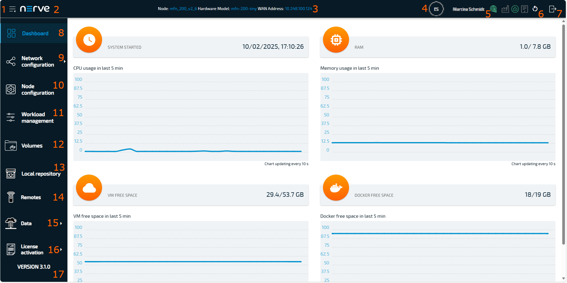
The dashboard of the Local UI is the default screen after the log in. Usage statistics of the Nerve Device are displayed in the window with more options in the menu on the left side.
| Term | Description |
|---|---|
| Burger menu (1) | Expand and collapse the left-hand menu by selecting this. |
| Nerve logo (2) | Select this to return to the dashboard and reload the page. |
| Node details (3) | Details of the node are displayed here, showing the name of the node in the Management System, the hardware model and the WAN address of the node. |
| Node details (4) | Indicates which user is currently logged in |
| Status icons (5) | These icons indicate different statuses or functions of the node. If the icon is displayed in green, the status is enabled. If the icon is shown in grey, the status is disabled. The following list provides an overview of the icons and their meanings.  Select this icon to enable or disable the network connection. Select this icon to enable or disable the network connection.  Select this icon to enable or disable the production mode. If the icon is shown in blue the production mode is reconfiguring. For more information refer to Production mode. Select this icon to enable or disable the production mode. If the icon is shown in blue the production mode is reconfiguring. For more information refer to Production mode. Selecting this icon will start an integrity check on the system. For more information refer to Integrity check. Selecting this icon will start an integrity check on the system. For more information refer to Integrity check. |
| Reboot Node (6) | Selecting this will reboot the node after a confirmation dialog. Select YES to initiate the reboot. All running workloads will be stopped. After the reboot, the workloads will return to their previous state. Running workloads will be started. Stopped workloads will stay stopped. |
| Log out (7) | Select this to log out of the Local UI. |
| Dashboard (8) | Select this to display the dashboard containing the system metrics — graphs showing available resources of the Nerve Device and their usage over time. |
| Network configuration (9) | This menu allows to configure the Ethernet ports of the Nerve Device, as well as proxy settings for the node. |
| Node configuration (10) | Configure data such as the Management System URL that the node will connect to or the serial number of the node here. The information required to register a node in the Management System is configured in this menu. Also, passwords can be changed here. |
| Workload management (11) | Select this menu for control options for deployed workloads and manual deployment of workloads. |
| Volumes (12) | Select this menu to delete, import or, export Docker volumes on the node. |
| Local Repository (13) | Find settings for the configuration of a local workload repository here. |
| Remotes (14) | Manage incoming and active remote connections here. |
| Data (15) (Optional) | Access the Nerve Data Services here. This item only appears once the Data Services workload has been deployed. Refer to Nerve Data Services for more information. |
| License activation (16) | This is the UI that is used for activating licenses. Use this menu to check currently activated licenses. |
| Node version (17) | This is the currently installed version of the node. |
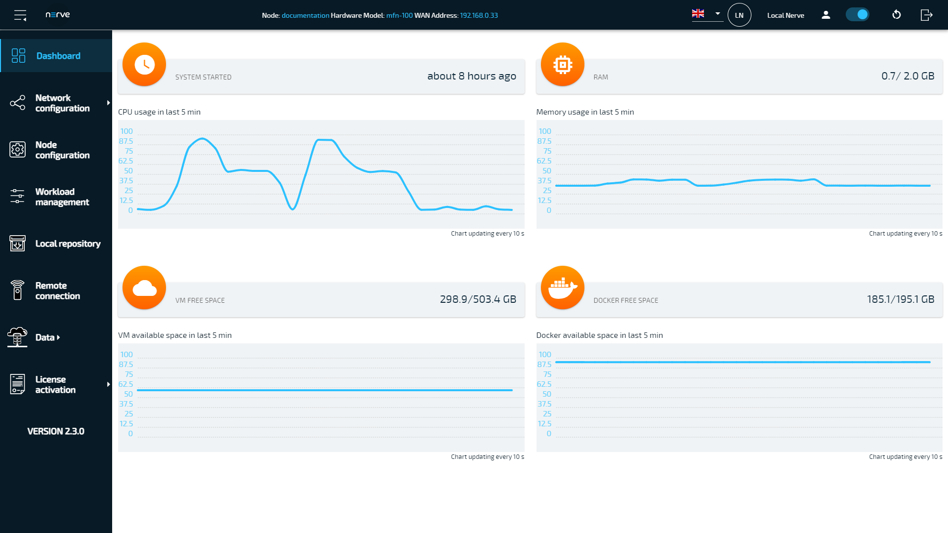
System metrics
The graphs in the Local UI dashboard show available resources of the Nerve Device and their usage over time. The y-axis displays percentages and the x-axis is updated every 10 seconds, showing a time span of 5 minutes. The percentages displayed are always in relation to the maximum of the available resource:
| Item | Description |
|---|---|
| SYSTEM STARTED | This shows how long the Nerve Device has been running. If the device is restarted, this value is reset. |
| CPU usage in last 5 min | The graph here shows the percentage of processing power that is being used. This includes CPUs that have been assigned to VMs and Docker containers. |
| RAM | This shows how much memory is used (left value) and how much memory is available in total (right value). Example: 0.3/1.9 GB Note that the total amount of memory the Nerve Device offers is not shown here. This is the memory that is available for the host. |
| Memory usage in last 5 min | Similar to CPU usage, the graph shows the percentage of memory used. This includes memory that has been assigned to VMs or Docker containers. |
| VM FREE SPACE | Virtual machines have their dedicated virtual partition (Logical Volume Manager). The values show how much of this partition is used (left value) and how much is available in total (right value). Example: 86.5/238.5 GB |
| VM free space in last 5 min | This graph shows the percentage of space that is being used by the Logical Volume Manager. |
| DOCKER FREE SPACE | Similar to VM free space, Docker containers have their dedicated virtual partition. The values show how much of this partition is used (left value) and how much is available in total (right value). Example: 2.9/40.3 GB |
| Docker free space in last 5 min | This graph shows the percentage of space for Docker containers that is being used. |
Production mode
Enabling production mode reduces system exposure and helps prevent unauthorized node access by applying stricter security measures, such as SSH access restrictions and isolation of the CODESYS runtime.
Enable production mode
To enable production mode proceed as follows:
- Select the icon production mode in the upper right corner of the Local UI dashboard.
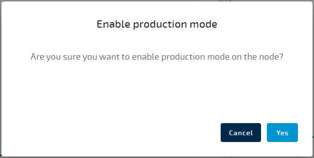
- Select Yes to enable production mode.
The icon production mode starts to blink in blue during reconfiguration.
Once production mode is enabled, the icon will turn green.
When production mode is enabled, the following SSH restrictions are applied:
- SSH (Port 22) is be blocked on all physical ports and exposed networks.
Note
SSH restrictions apply only for new sessions, already existing sessions are not terminated.
When production mode is enabled, the following CODESYS runtime isolation are applied:
- The CODESYS runtime cannot be accessed by the IDE via any interface or development workstation.
- All incoming communication to the CODESYS runtime is blocked.
- Existing sessions are terminated.
Note
CODESYS can still be accessed over the physical interface on the node for fieldbus connection and over internal network for communication with the relevant services or for user application.
Disable production mode
To disable production mode proceed as follows:
- Select the icon production mode in the upper right corner of the Local UI dashboard.
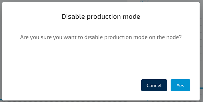 .
. - Select Yes to disable production mode.
If the icon production mode changes from green to grey, the production mode is disabled.
Integrity check
You can perform an integrity check to verify whether the settings comply with IEC 62443-4-2 CR 3.4.
To perform an integrity check proceed as follows:
- Enable production mode before starting an integrity check.
If the production mode is not enabled, the integrity check cannot be performed and an error will be displayed. - Select the icon integrity check in the upper right corner of the Local UI dashboard.
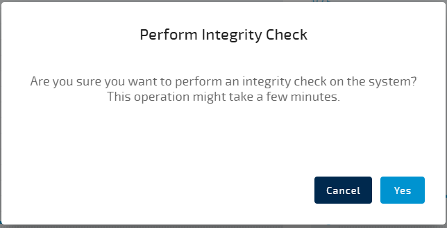 .
. - Select Yes to perform an integrity.
Hashes are compared to the baseline established at entering Production Mode.
Once the integrity check is finished, the icon will indicate the result by turning green on passing, or red on failure. .
If the integrity check fails, perform the following steps:
- Disable production mode.
- Enable production mode.
When production mode is re-enabled, the system recalculates hashes based on the current state of the monitored files and directories. As long as these files remain unchanged, the integrity checks will pass.
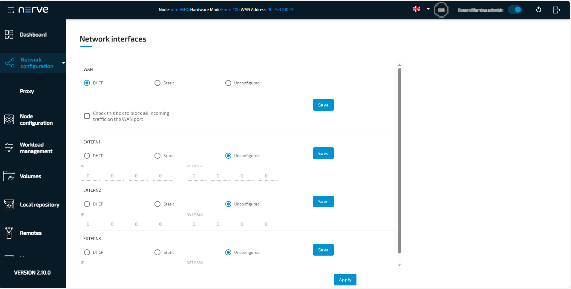
Local network configuration
From the Local UI, the Ethernet ports of the Nerve Device can be configured. Select Network configuration in the navigation on the left to reach this menu. The example below is of the MFN 100. The page is specific to the Nerve Device. The number and names of interfaces may differ.
Note
To reduce the risk of attacks, you can block all incoming traffic on the WAN interface, which will limit the potential entry points for attackers and decrease the overall attack surface. To do so select the checkbox Check this box to block all incoming traffic on the WAN port.
After activating the checkbox all currently established connections will stay intact, but further connection requests will be denied.
This setting does not affect defined port exports of docker workloads. Ports that are defined to be exposed on the WAN interface, either by explicitly selecting the WAN network, or implicitly by using the default bridge or any user defined network, will still be accessible on the WAN interface.
| Item | Description |
|---|---|
| DHCP | The IP address of the port will be assigned by the DHCP server. If an IP address has been assigned, it will be displayed here. |
| Static | By selecting Static, the IP address of the port needs to be manually defined. Enter the IP address and subnet mask under IP and NETMASK to set a static IP address. For the WAN interface, the GATEWAY, the preferred DNS as well as two alternative DNS can also be set.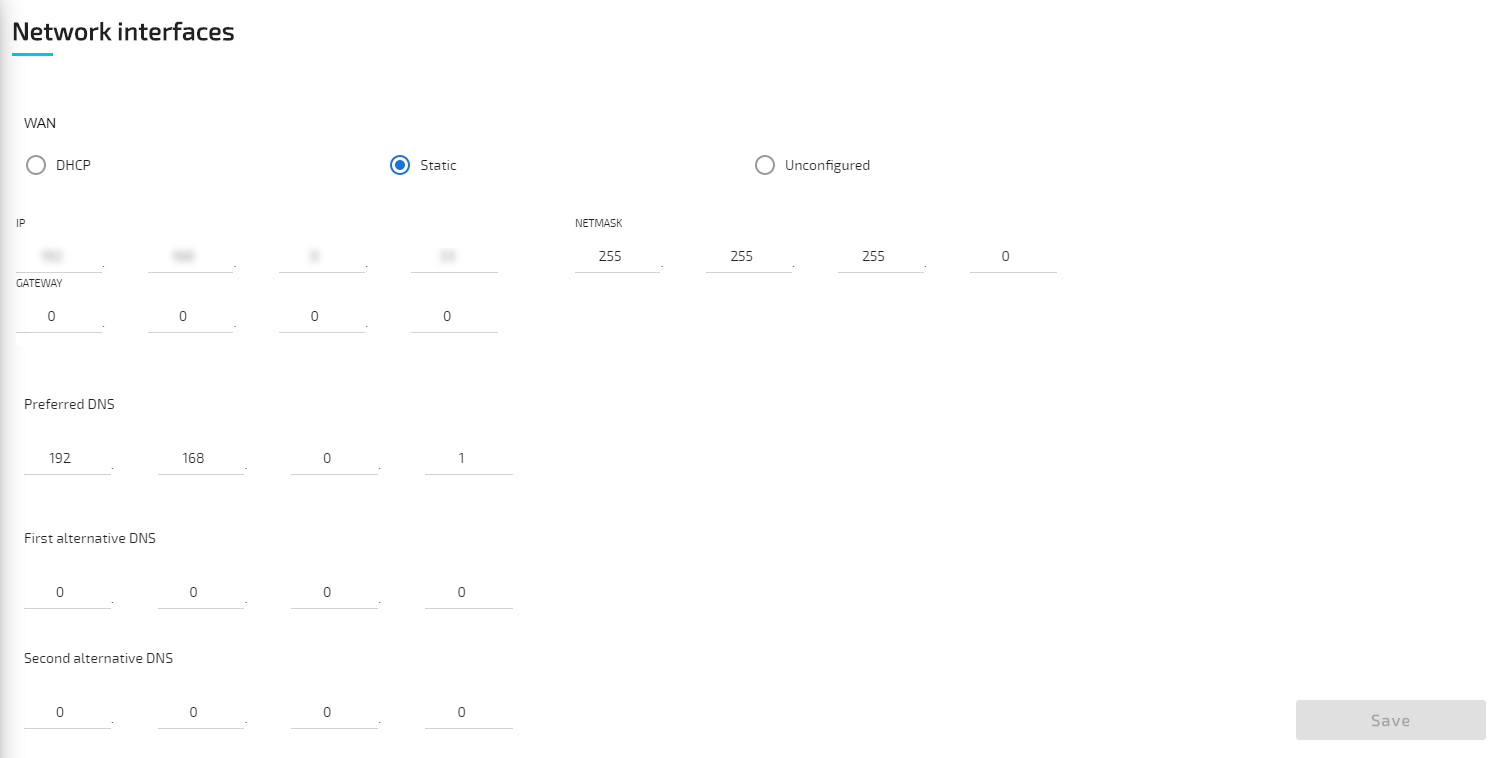 |
| Unconfigured | If Unconfigured is checked, the port is disabled for the host but can still be used for virtual machines with bridged interfaces. |
Note
For more information on networking and interfaces refer to the networking chapter.
Proxy settings
Network configuration settings can be extended with the possibility to specify proxy settings. In case a proxy server is present in the company network, these settings can be used to enable communication between the node and the Management System. The proxy settings define an HTTP/S proxy for the node with the possibility to specify credentials if they are requested, as well as exceptions. Note that the proxy settings affect the internal communication of the node towards the Management System, and the connections covered by the proxy settings are only those related to:
- the management of workloads on the node
- logs sent from the node to the Management System
- data transmitted from the Data Services Gateway
- the Debian Advanced Package Tool (APT)
Potential connections generated by workloads on the node do not use the node proxy settings.
Expand Network configuration > Proxy to reach the proxy settings.
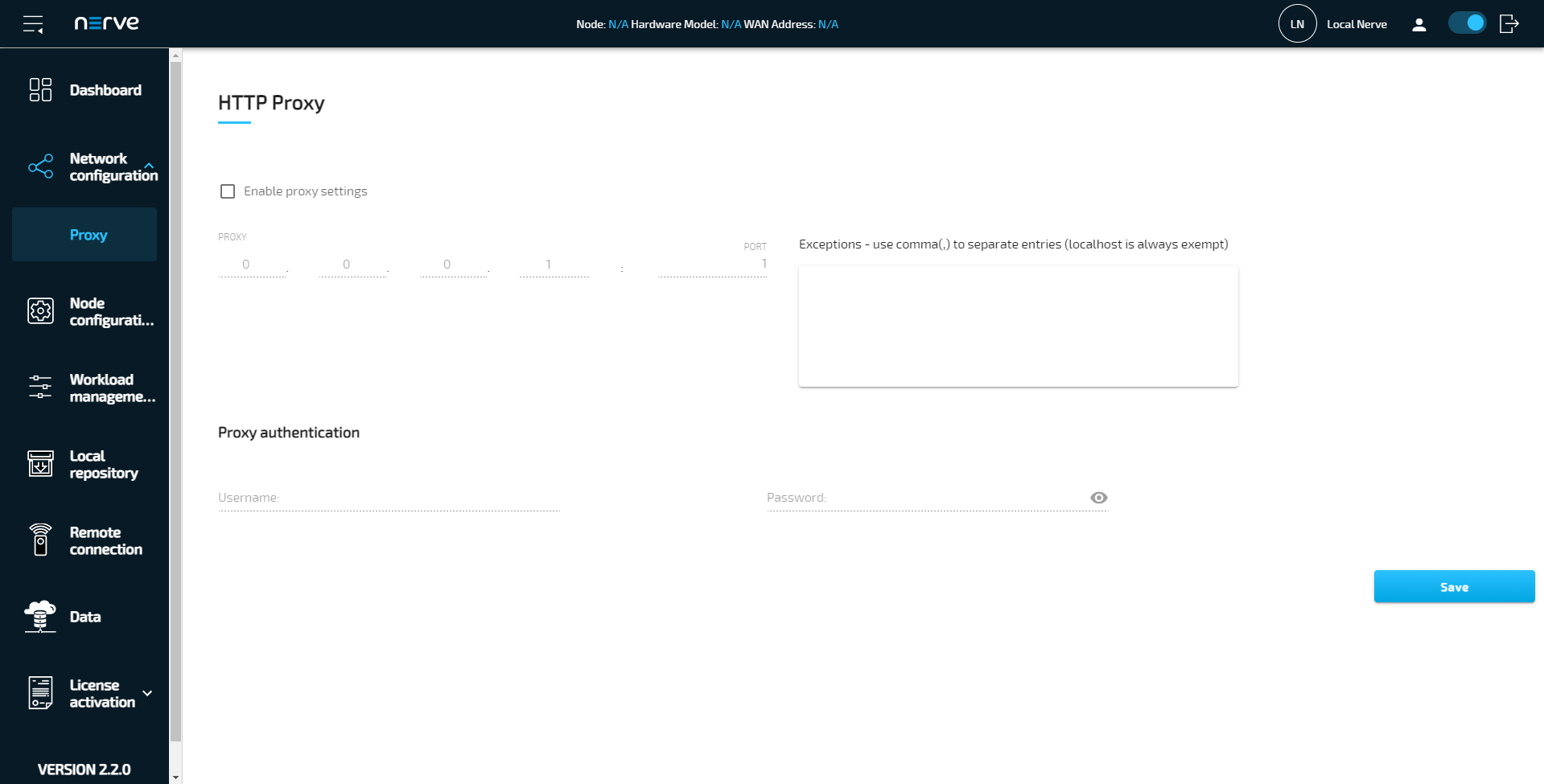
| Item | Description |
|---|---|
| Enable proxy settings | Tick the checkbox here to enable proxy settings. |
| PROXY | Enter the IP address of the proxy server here. |
| PORT | Enter the number of the port that is open for communication at the proxy server. |
| Exceptions - use comma(,) to separate entries (localhost is always exempt) | List IP addresses or hostnames of exceptions separated by a comma here. The node will directly communicate with the exceptions without using the proxy server. An example is a local workload repository that can be defined in the Local UI. Refer to Setting a local repository for more information. |
| Proxy authentication | Enter the Username and Password required to access the proxy server. This is optional. If the proxy server does not require login credentials, the fields can be left empty. |
Select Save to apply the configuration. To undo the proxy settings, uncheck Enable proxy settings and select Save.
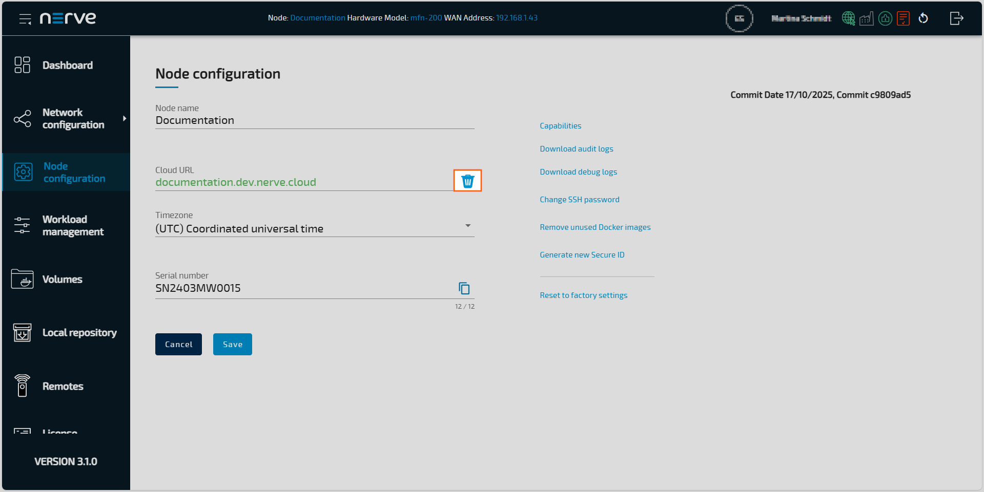
Node configuration
The first part of registering a node in the Management System is performed in the Local UI. Node details and information required for registering a node in the Management System are configured under Node configuration.

- Select Node configuration in the navigation on the left.
-
Enter the following information:
Item Description Node name Enter the name of the node to be used in the Management System. Cloud URL Enter the URL of the Management System without the protocol, e.g example.nerve.cloud.
The URL font color will turn to green if the URL is correct and the node can reach the Management System. If the URL font color turns to red, check the URL for errors and whether network access is established.Timezone This setting is optional. Select a location from the list to have the time zone of the node displayed in the Management System. An overview of the available timezones you can find in the table Available timezones Serial number Enter a serial number with a minimum of 12 characters.
Note that this serial number can be freely defined. It is required for node registration in the Management System and serves as a means of identification. Entering the serial number that is printed on the Nerve Device is not required but recommended. -
Select Save.
A new dialog box appears. -
Enter your credentials to submit the configuration of the node.
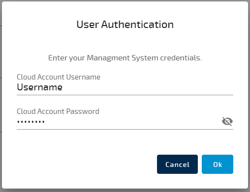
-
Select Ok.
If the user settings include MFA, a new dialog box will appear. - Enter the MFA authentication code. This code must be read from the authenticator app and entered into the provided field.
The node is now available in the Management System
Additional menus
Additional menus are available on this page are listed below.
| Item | Description |
|---|---|
| Capabilities | Display the node capabilities. |
| Download audit logs | This function allows you to download the audit logs from the node as a ZIP package to your workstation. This download option allows you to download audit logs from the node even when the node is offline. |
| Download debug logs | With this function, you can download the debug logs from the node in a tar.gz package to your workstation. These debug logs help support engineers in case of troubleshooting incidents. Attach the log files when creating a ticket via the TTTech Industrial support portal. |
| Change SSH password | Change the node admin SSH password Changing the host SSH password. |
| Remove unused Docker images | Select this menu to remove Docker images which are not related to any workload on the node. |
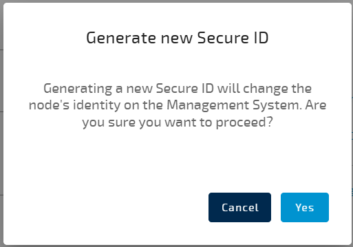
| Generate new Secure ID | You can generate a new secure ID for the node to improve security or reset access if there is a suspicion that it has been compromised.
|
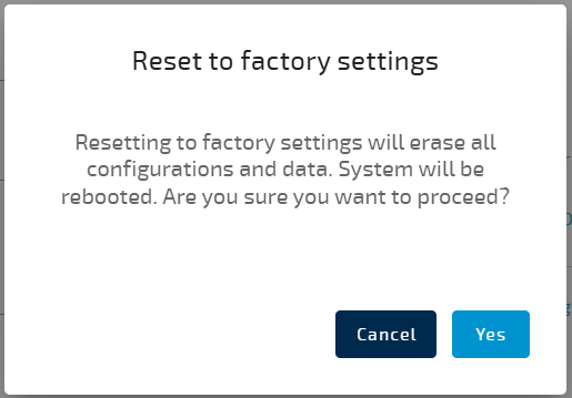
| Reset to factory settings | Using this function will permanently remove all custom data from the node. The following data will be deleted:
|
Available timezones
| Header Text | Value |
|---|---|
| (GMT-12:00) International Date Line West | Etc/GMT-12 |
| (GMT-11:00) Midway Island, Samoa | Pacific/Pago_Pago |
| (GMT-10:00) Hawaii | Pacific/Honolulu |
| (GMT-09:00) Alaska | America/Anchorage |
| (GMT-08:00) Pacific Time (US and Canada); Tijuana | America/Los_Angeles |
| (GMT-07:00) Mountain Time (US and Canada) | America/Denver |
| (GMT-07:00) Chihuahua, La Paz, Mazatlan | America/Chihuahua |
| (GMT-07:00) Arizona | America/Phoenix |
| (GMT-06:00) Central Time (US and Canada) | America/Chicago |
| (GMT-06:00) Saskatchewan | Canada/Saskatchewan |
| (GMT-06:00) Guadalajara, Mexico City, Monterrey | America/Mexico_City |
| (GMT-06:00) Central America | America/Guatemala |
| (GMT-05:00) Eastern Time (US and Canada) | America/New_York |
| (GMT-05:00) Indiana (East) | America/Indiana/Indianapolis |
| (GMT-05:00) Bogota, Lima, Quito | America/Bogota |
| (GMT-04:00) Atlantic Time (Canada) | America/Halifax |
| (GMT-04:00) Caracas, La Paz | America/Caracas |
| (GMT-04:00) Santiago | America/Santiago |
| (GMT-03:30) Newfoundland and Labrador | America/St_Johns |
| (GMT-03:00) Brasilia | America/Sao_Paulo |
| (GMT-03:00) Buenos Aires, Georgetown | America/Argentina/Buenos_Aires |
| (GMT-03:00) Greenland | America/Godthab |
| (GMT-02:00) Mid-Atlantic | Etc/GMT-2 |
| (GMT-01:00) Azores | Atlantic/Azores |
| (GMT-01:00) Cape Verde Islands | Atlantic/Cape_Verde |
| (UTC) Coordinated universal time | Etc/UTC |
| (GMT) Greenwich Mean Time: Dublin, Edinburgh, Lisbon, London | Europe/London |
| (GMT) Casablanca, Monrovia | Africa/Casablanca |
| (GMT+01:00) Belgrade, Bratislava, Budapest, Ljubljana, Prague | Europe/Belgrade |
| (GMT+01:00) Sarajevo, Skopje, Warsaw, Zagreb | Europe/Warsaw |
| (GMT+01:00) Brussels, Copenhagen, Madrid, Paris | Europe/Paris |
| (GMT+01:00) Amsterdam, Berlin, Bern, Rome, Stockholm, Vienna | Europe/Berlin |
| (GMT+01:00) West Central Africa | Africa/Lagos |
| (GMT+02:00) Bucharest | Europe/Bucharest |
| (GMT+02:00) Cairo | Africa/Cairo |
| (GMT+02:00) Helsinki, Kiev, Riga, Sofia, Tallinn, Vilnius | Europe/Helsinki |
| (GMT+02:00) Athens, Istanbul, Minsk | Europe/Athens |
| (GMT+02:00) Jerusalem | Asia/Jerusalem |
| (GMT+02:00) Harare, Pretoria | Africa/Johannesburg |
| (GMT+03:00) Moscow, St. Petersburg, Volgograd | Europe/Moscow |
| (GMT+03:00) Kuwait, Riyadh | Asia/Riyadh |
| (GMT+03:00) Nairobi | Africa/Nairobi |
| (GMT+03:00) Baghdad | Asia/Baghdad |
| (GMT+03:30) Tehran | Asia/Tehran |
| (GMT+04:00) Abu Dhabi, Muscat | Asia/Dubai |
| (GMT+04:00) Baku, Tbilisi, Yerevan | Asia/Baku |
| (GMT+04:30) Kabul | Asia/Kabul |
| (GMT+05:00) Ekaterinburg | Asia/Yekaterinburg |
| (GMT+05:00) Islamabad, Karachi, Tashkent | Asia/Karachi |
| (GMT+05:30) Chennai, Kolkata, Mumbai, New Delhi | Asia/Kolkata |
| (GMT+05:45) Kathmandu | Asia/Kathmandu |
| (GMT+06:00) Astana, Dhaka | Asia/Dhaka |
| (GMT+06:00) Sri Jayawardenepura | Asia/Colombo |
| (GMT+06:00) Almaty, Novosibirsk | Asia/Almaty |
| (GMT+06:30) Yangon (Rangoon) | Asia/Yangon |
| (GMT+07:00) Bangkok, Hanoi, Jakarta | Asia/Bangkok |
| (GMT+07:00) Krasnoyarsk | Asia/Krasnoyarsk |
| (GMT+08:00) Beijing, Chongqing, Hong Kong SAR, Urumqi | Asia/Shanghai |
| (GMT+08:00) Kuala Lumpur, Singapore | Asia/Kuala_Lumpur |
| (GMT+08:00) Taipei | Asia/Taipei |
| (GMT+08:00) Perth | Australia/Perth |
| (GMT+08:00) Irkutsk, Ulaanbaatar | Asia/Irkutsk |
| (GMT+09:00) Seoul | Asia/Seoul |
| (GMT+09:00) Osaka, Sapporo, Tokyo | Asia/Tokyo |
| (GMT+09:00) Yakutsk | Asia/Yakutsk |
| (GMT+09:30) Darwin | Australia/Darwin |
| (GMT+09:30) Adelaide | Australia/Adelaide |
| (GMT+10:00) Canberra, Melbourne, Sydney | Australia/Sydney |
| (GMT+10:00) Brisbane | Australia/Brisbane |
| (GMT+10:00) Hobart | Australia/Hobart |
| (GMT+10:00) Vladivostok | Asia/Vladivostok |
| (GMT+10:00) Guam, Port Moresby | Pacific/Guam |
| (GMT+11:00) Magadan, Solomon Islands, New Caledonia | Asia/Magadan |
| (GMT+12:00) Fiji Islands, Kamchatka, Marshall Islands | Pacific/Fiji |
| (GMT+12:00) Auckland, Wellington | Pacific/Auckland |
| (GMT+13:00) Nuku'alofa | Pacific/Tongatapu |
Offboarding a node from the Management System
Data loss warning
When offboarding a node from the Management System, all user data except for the installed license will be deleted. That includes
- Workloads
- Docker volumes
- User accounts
A node can be offboarded from the specified Management System by selecting the offboard button next to the Management System URL.
When the node is offboarded from the Management System, the respective node information, including the defined remote connections, will be removed from the Management System.
All user data will be removed from the node, except for the installed license. Workloads will be undeployed, docker volumes and virtual machine disks will be removed, Codesys workloads, remanent variables, and 3rd party licenses will be removed. All user accounts will be removed, and the default admin account will be reactivated.
Make sure to have the default credentials at hand before performing this action, as the current user will be logged out, and the only possibility to login again is with the credentials of the default admin user.
Changing the affiliated Management System
Changing the affiliated Management System works in a similar manner like registering a node for the first time at a Management System.
Workload management
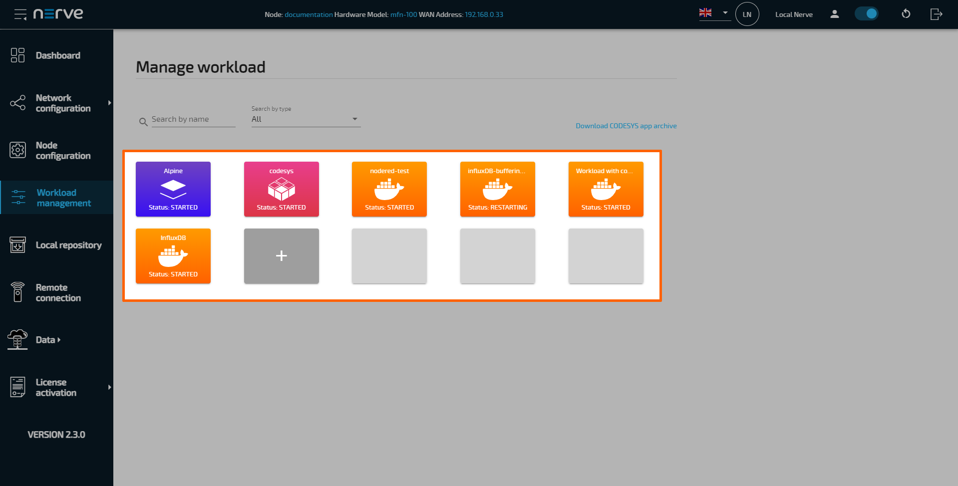
Deployed workloads can be controlled in the Local UI. Select Workload management in the navigation menu on the left-hand side for an overview of all deployed workloads. Then, select a workload to reach the interface for controlling workloads running on the Nerve Device. If there is a large number of workloads deployed, filter the list by name or by type. Enter a search query under Search by name to filter the list by name. Select All, VM, Codesys and Docker from the drop-down menu to filter workloads by type.
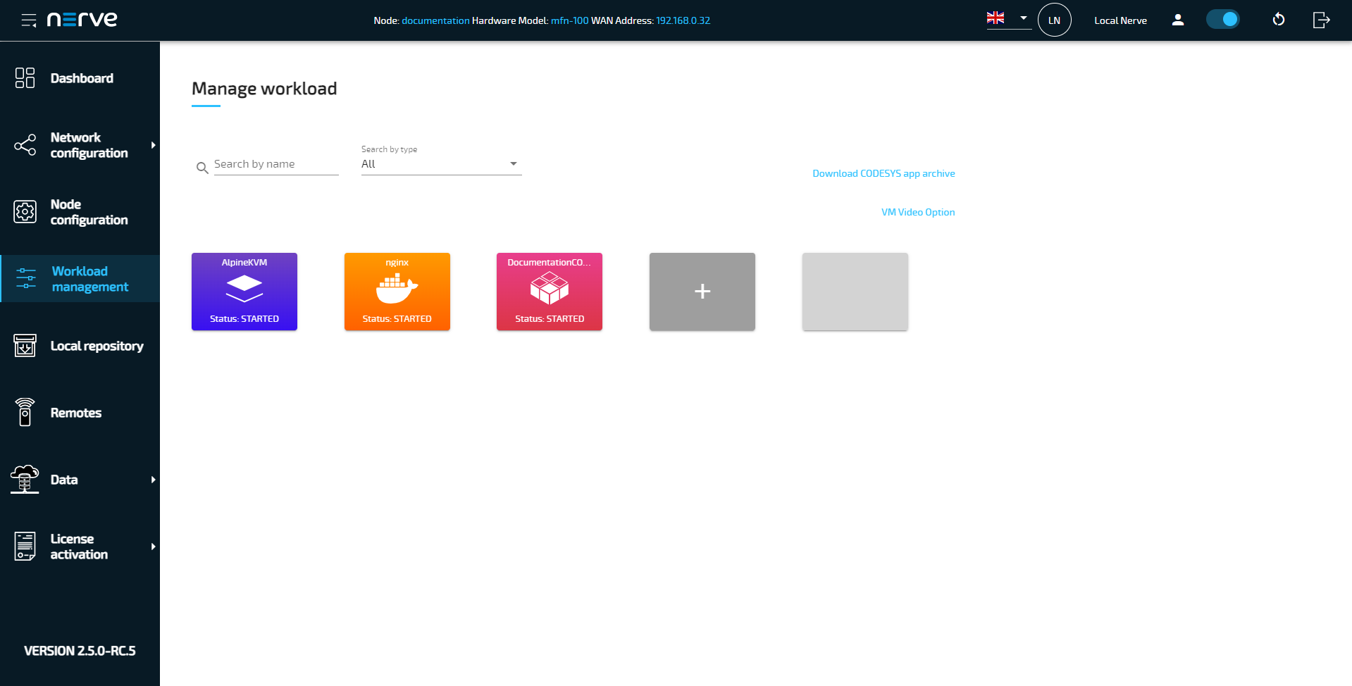
Note that CODESYS workloads can only be controlled in the Local UI, as operation of a CODESYS workload may have an impact on machine operation and therefore should not be controlled remotely. Virtual Machine workloads and Docker workloads can also be controlled in the Management System. Therefore, the screenshot and description below focuses on CODESYS workload specifics only. Refer to Workload control for general information on workload control.
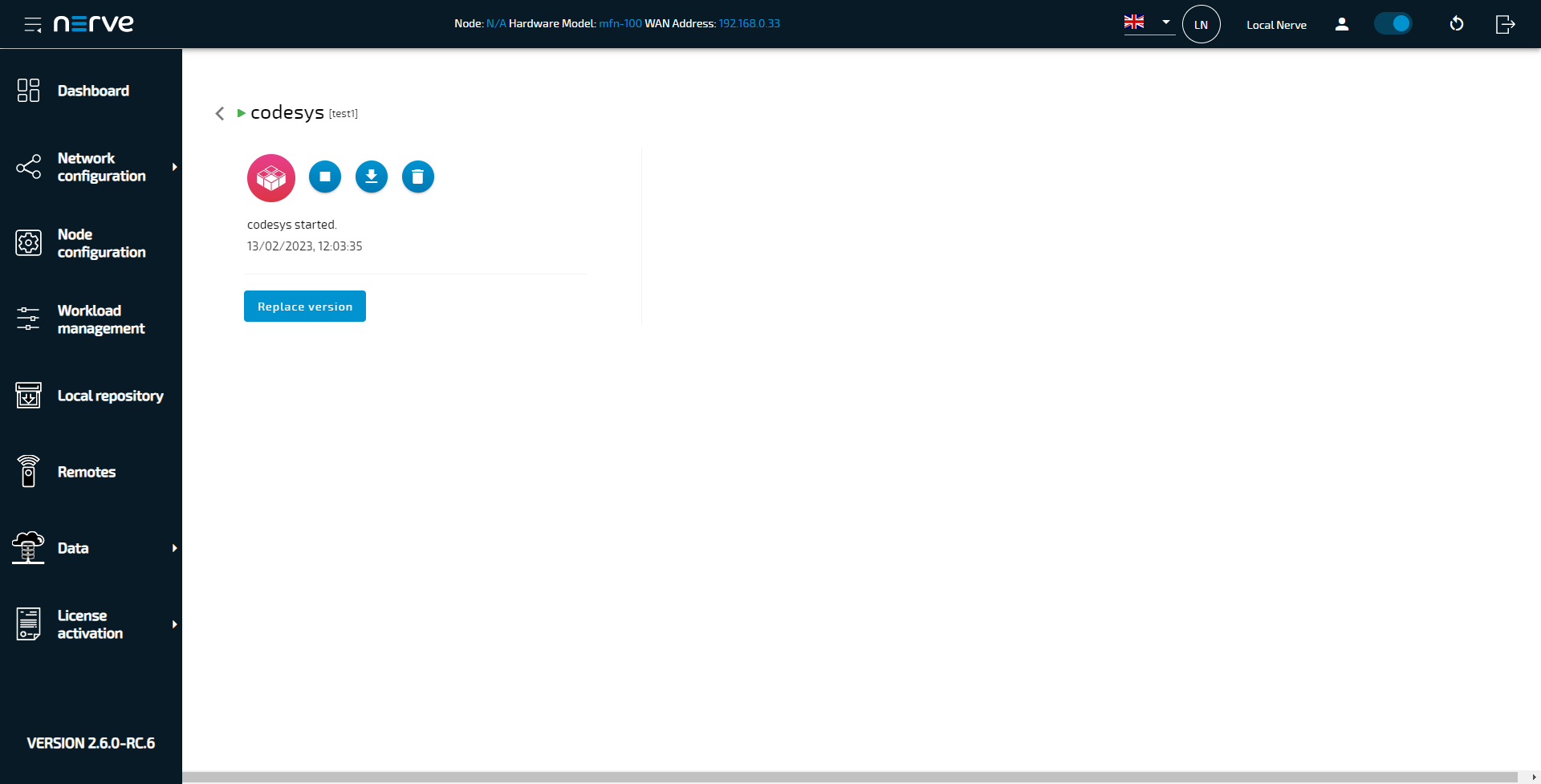
| Item | Description |
|---|---|
| Replace version | Select this to replace the current workload version with a different one as a TAR file. Note that the new workload version must be exported from the Management System first. Refer to Updating a deployed workload in the Local UI below for more information. |
| Control panel | Play/Stop button This button starts or stops the CODESYS workload depending on its current state:
Download button The download button initiates the download of the CODESYS archive as a ZIP file. |
| Message window | The message window displays the latest message the workload has sent out including how much time has passed since it was sent out. The type of message that is displayed here depends on the workload. CODESYS workloads have the following set of messages:
|
All changes performed in the Local UI are reflected in the Management System.
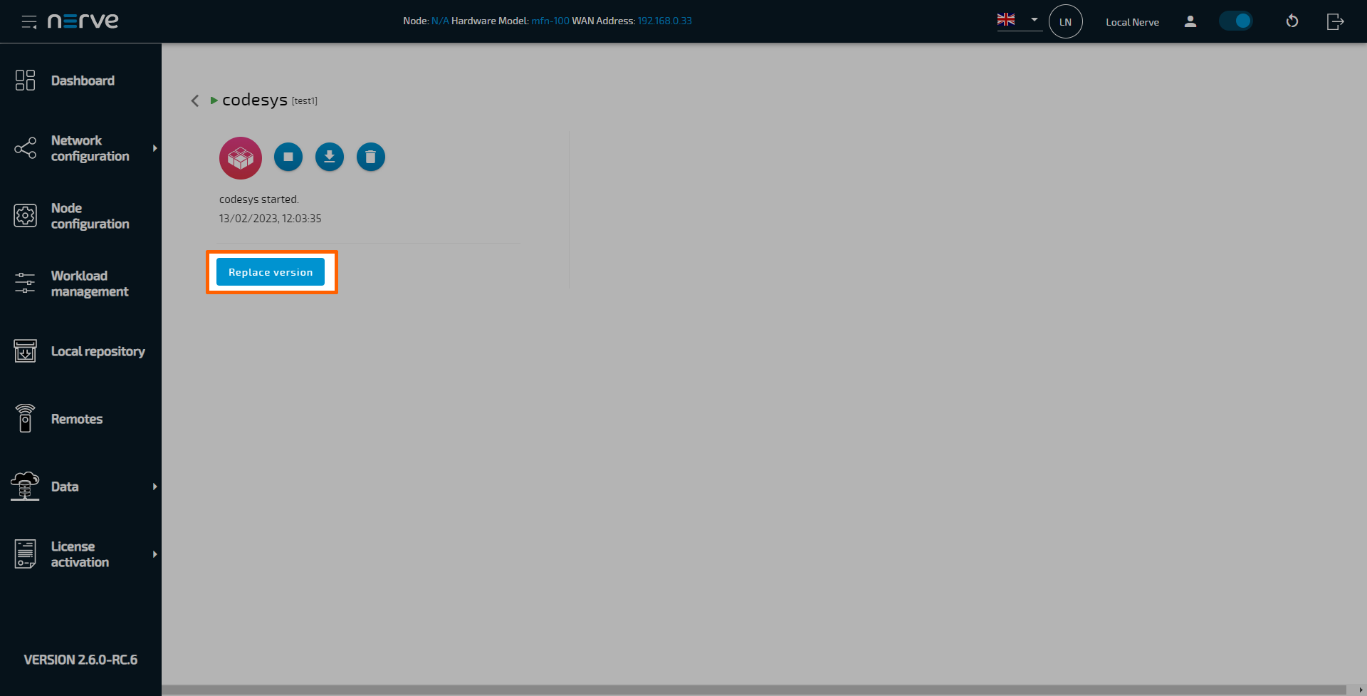
Replacing the version of a deployed workload in the Local UI
Versions of deployed CODESYS and Docker workloads can be replaced by other versions through the workload control screen. Replacing the workload version is a quick way to deploy a new version of the same workload. However, note that the new workload version needs to be exported first when replacing a workload version through the Local UI. Refer to Exporting a workload for more information on how to export a workload version in the Management System.
- Select Workload management in the navigation on the left.
-
Select the tile of a workload with multiple versions.
-
Select Replace version.
-
Select the plus icon to open the file browser.
- Select the exported workload version update in TAR format.
-
Select Open to add the exported workload update.
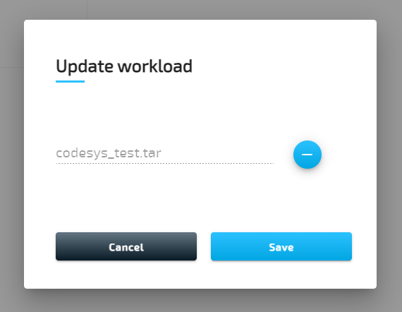
-
Select Save.
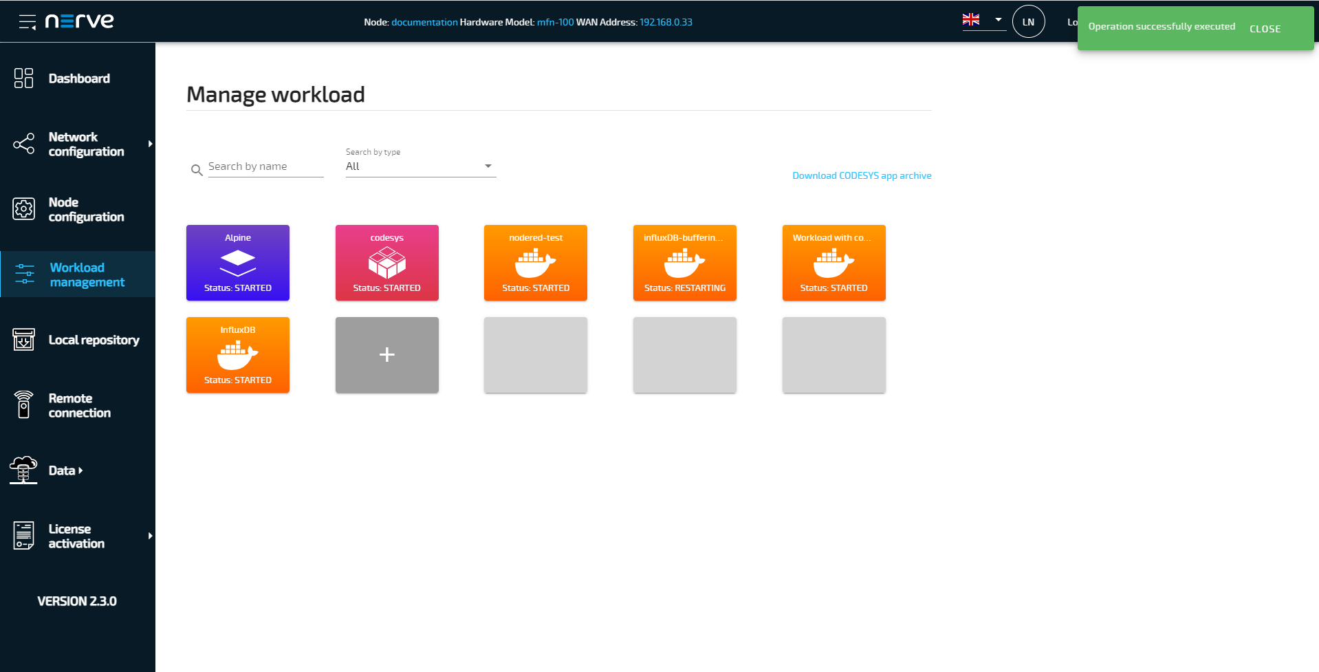
This starts the replacement of the workload version. Once the deployment of the new version is completed, the Local UI will return to the workload management screen and display a green success message in the upper-right corner.
Local workload deployment
Workloads that have been provisioned in the Management System can be exported and then deployed directly through the Local UI. Refer to the workloads chapter on how to export a workload before following the instructions below.
- Export a workload in the Management System.
- Switch to the Local UI.
- Select Workload management in the navigation on the left side.
-
Select the plus tile in the middle.
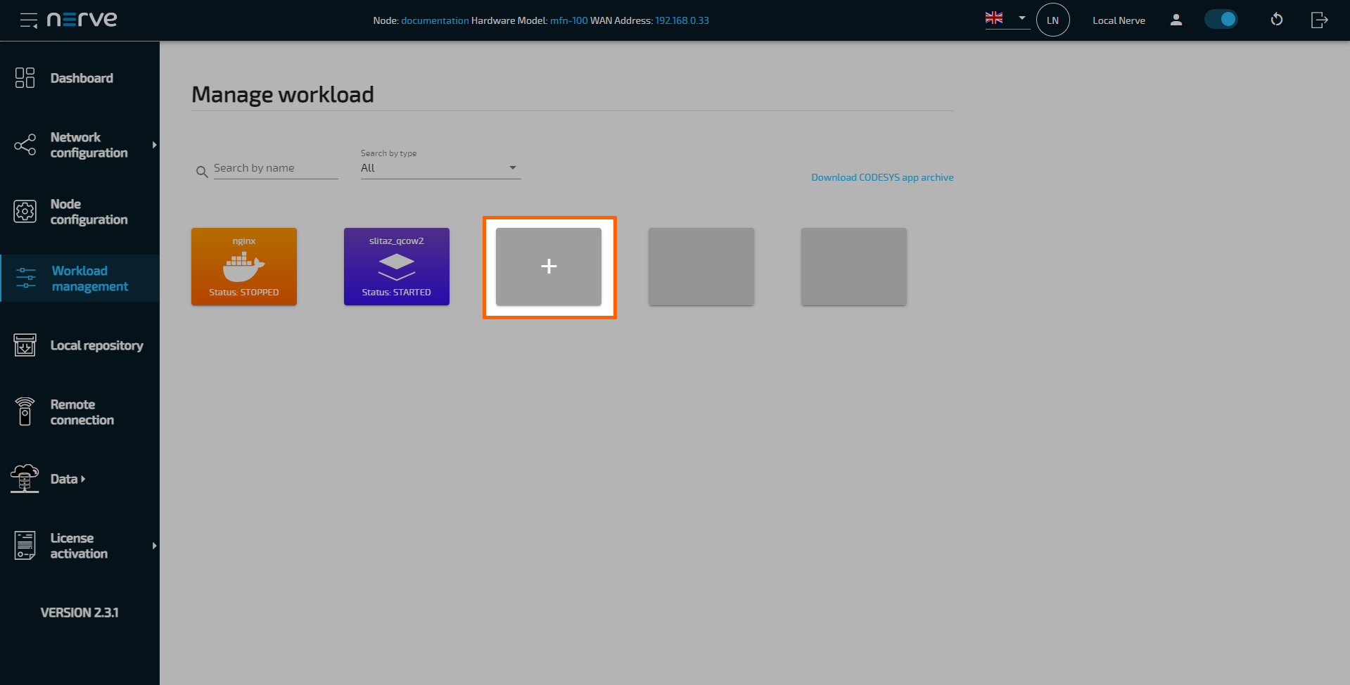
-
Select the plus symbol to open the file browser.
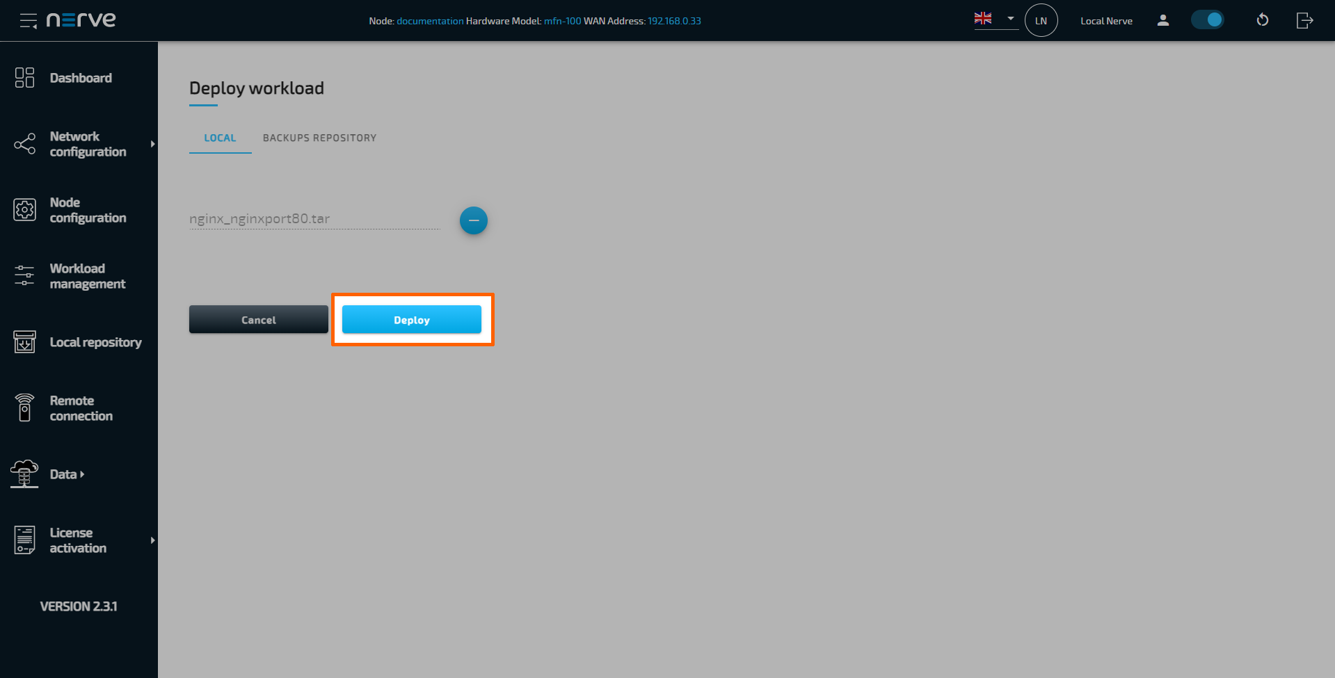
- Add the TAR file containing the exported workload.
-
Select Save to deploy the workload.
Volumes
The Volumes menu provides a list of all available Docker volumes on the node. The definition of the Docker volumes takes place during the provisioning of a Docker workload via the Management System (for more information refer to Provisioning a Docker workload).
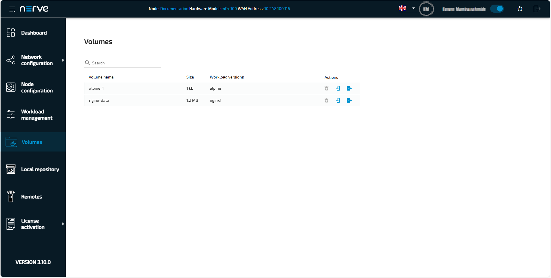
The list contains the following information:
- Volume name given during provisioning the Docker workload,
- The memory Size of the Docker volume.
- The Workload version to which the Docker volume is assigned to.
| Actions | Items and Description |
|---|---|
| Delete | Select the garbage can icon Note that you cannot delete Docker volumes from the node, when they are assigned to a Docker workload version. This is indicated by a gray garbage can icon |
| Import | To import data to a Docker volume, proceed as follows:
|
| Export | To export data from a Docker volume, select the blue export icon
|
Setting a local repository
If desired, the required files for deploying workloads can be stored in a local repository that does not require internet connection. In doing so, the workload image files for deployment are taken from a user defined repository instead of the workload repository in the Management System.
Refer to Exporting a Workload for information on how to obtain the workload images. Also note that every workload needs to be provisioned in the Management System once before the image files can be transferred to a local repository.
A web server that services static files is required. Popular web servers like Nginx or Apache HTTP Server can be used, as well as a Network-attached storage (NAS) device. Recommended are:
- the NodeJS http-server for Linux
- the built-in Internet Information Services (IIS) for Windows
The IIS for Windows needs to be activated first in newer versions of Windows like Windows 8 and Windows 10.
- Open the Control Panel
- Navigate to Control Panel > Programs > Programs and Features.
- Select Turn Windows features on or off
- Tick the checkbox next to Internet Information Services.
Note that ticking the checkbox will only enable the components required to publish a web site. Expand the folder to select other needed features. - Select OK.
With this the IIS can be used on a Windows machine. Take the following steps to enable the hosting of the workload images. The steps below are not carried out in detail as they are only serving as a guideline.
- Remove all files from the document root. The default location of the document root is
C:\inetpub\wwwroot. - Copy the TAR files of the workloads that have been exported from the Management System to the document root.
- Enable directory listing.
- Test the web server by opening http://localhost in a web browser.
- Test if a computer can be reached from another computer in the network.
Note
Note that all served files can be accessed from all computers connected to the same network.
For more information, refer to the IIS documentation. Follow the instructions below to enable a local repository for a node:
- Select Local Repository in the navigation on the left.
-
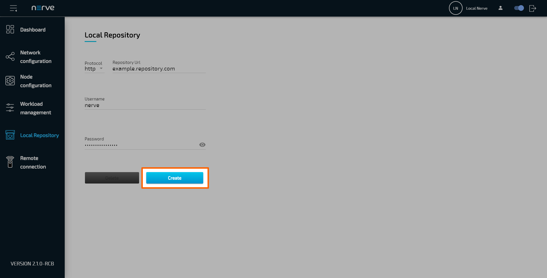
Enter the following information:
Item Description Protocol Select the protocol for communication with the local repository: http or https. Repository URL Enter the URL through which the web server hosting the workload images can be accessed. Username If login credentials have been defined for the web server, enter the username for accessing the web server hosting the workload images. Password If login credentials have been defined for the web server, enter the password for accessing the web server hosting the workload images. -
Select Create to finish the setup.
If a local repository is defined in the Local UI, the Management System will look for the workload images in the local repository first when a workload is deployed to this node. If the workload image is not present in the local repository, the workload repository in the Management System will be used instead. To revert back to using the repository of the Management System, select Local Repository in the navigation on the left and select Delete.
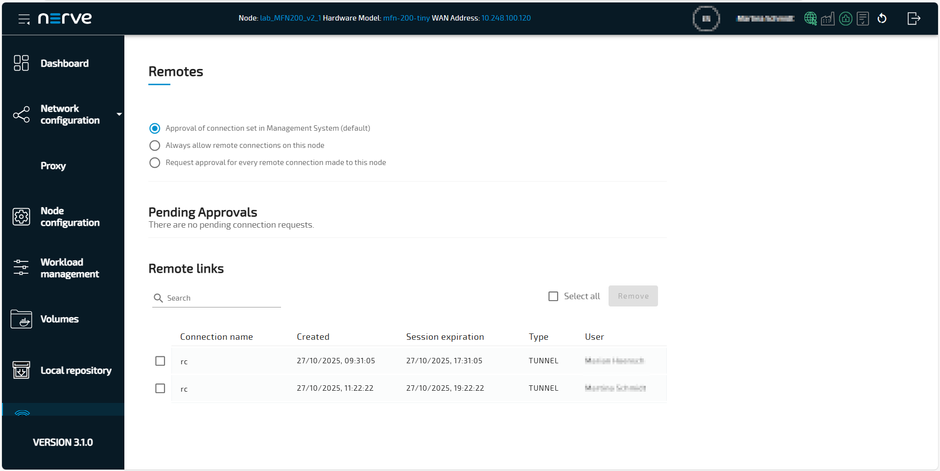
Managing remote connections
The behavior of nodes for remote connections is defined by the local settings and by the remote connection configuration in the Management System. Refer to Remote connections for more information.
| Item | Description |
|---|---|
| Settings | Set the be behavior of remote connections to the node |
| Pending Approvals | Incoming connection requests are displayed here. Select Approve to accept the remote connection. Selecting Cancel denies the incoming request. This setting is only valid when Local acknowledgment is set to Yes in the remote connection configuration in the Management System. |
| Remote links | Connection requests that have been approved and are currently open are listed here. |
Approval of remote connection settings
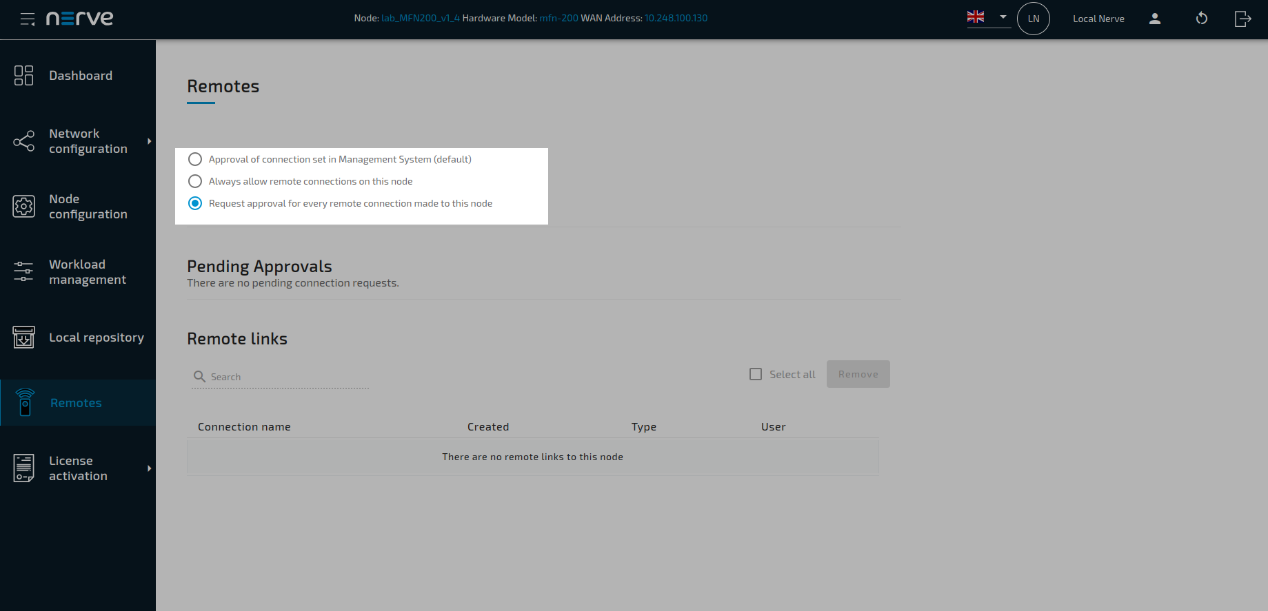
Three options are available:
- Approval of connection set in Management System to approve the remote connection as defined in the Management System
- Always allow remote connections to automatically approve all remote connection requests. This setting is only valid when Local acknowledgment is set to Yes in the remote connection configuration in the Management System.
- Request approval for every connection made to this node to force approval of all remote connection in the Local UI, independently of the settings in the Management System
Approving a remote connection
Local approval for remote connections can be configured in the Management System. Set Local acknowledgment to Yes when configuring a remote connection. When set to Yes, every remote connection has to be approved in the Local UI before it can be established. If approval for an incoming remote connection is pending, a notification bubble appears next to Remote connections in the navigation on the left.
- Select Remote connections in the navigation on the left.
- Search for incoming remote connections under Pending Approval.
-
Select Approve on the right for the remote connection that shall be established.
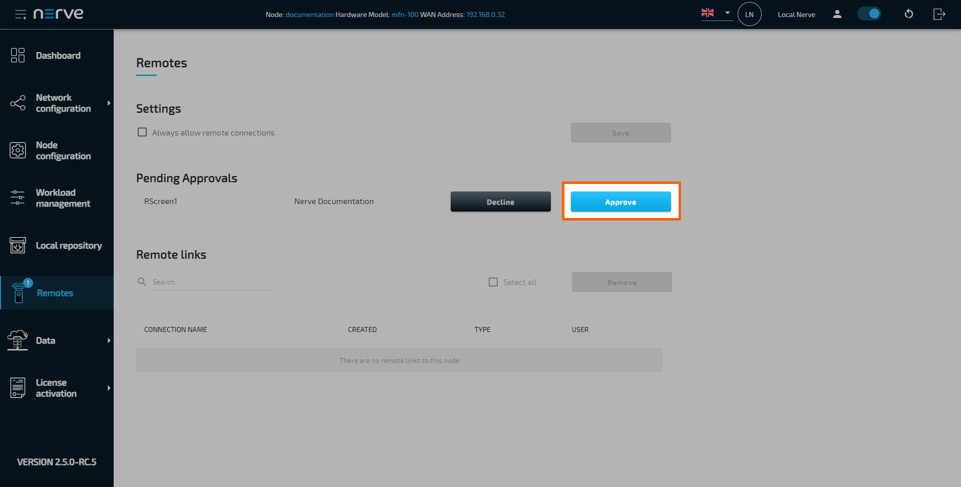
Once approved, the open connection will be displayed under Remote links below. Displayed are the name, creation and expiration dates of the remote connection, as well as the user currently using it. If the same remote connection is used by multiple users, multiple entries of the same remote connection are shown with different users.
Audit logs for nodes
Audit logs are a systematic and chronological record of events, activities, or transactions within a node. The node logs auditable events in both online and offline state.
Audit logs can also be viewed for the Management System.
These logs capture a wide range of information, including who performed an action, what the action was, when it occurred, and the outcome of the action. As such, they are a distinct security capability, providing forensics capability and traceability about past actions, and are crucial for several purposes, such as security, compliance, troubleshooting, and performance monitoring.
Note
Audit logs for the nodes are stored in OpenSearch for up to 6 months when it is online.
If the node is offline, the amount of the stored logs is limited device’s storage.
Access the audit logs for the node
The audit logs for the nodes are presented in an OpenSearch dashboard.
Note
Consider that shipping audit logs from the node to the OpenSearch can take up to 60 s.
Access to the Audit Logs within the Local UI
In case the node is offline (the node is not connected to the Management system) you can view the audit logs for the node via the Local UI.
- Connect to the designated nerve device via the local UI - API (refer to Connecting to the Local UI)
- Open the Node configuration.
- Select Audit logs.
Note
Audit logs obtained from the local UI directly are with timestamps of the GMT / UTC + 0 timezone.
Access to the OpenSearch dashboard within the Management System
- Navigate in the Management System to the node tree.
- Select the node for which the audit logs are needed.
- Select the tab Logs.
-
Select TRIGGERED FROM THE MANAGEMENT SYSTEM or TRIGGERED FROM THE NODE.
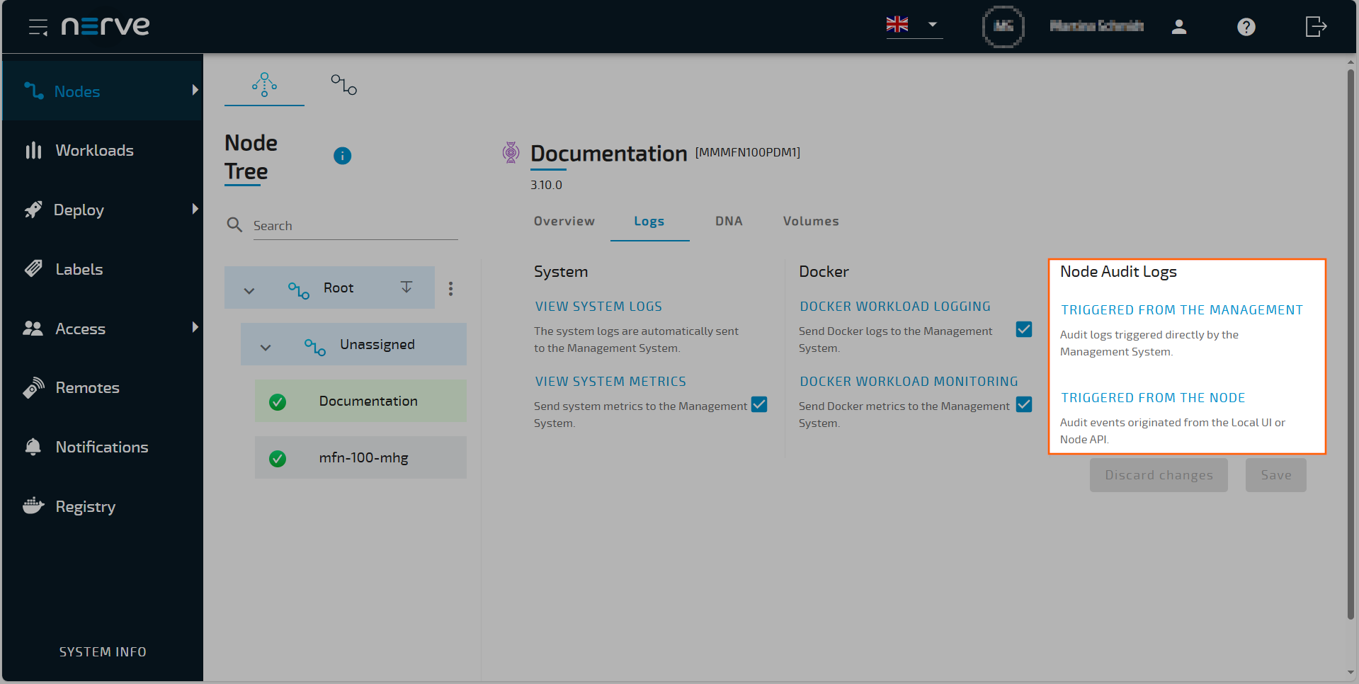 An OpenSearch Dashboard window for MS Audit logs or Node Audit logs will open in a new browser tab, showing relevant log entries for the selected node. See the logging page of the Management system for more details.
Note
If the node is offline, audit logs can be downloaded in ZIP format via an API endpoint available on the node. For more information about the OpenAPI specification under audit Logs, refer to the Nerve Node API
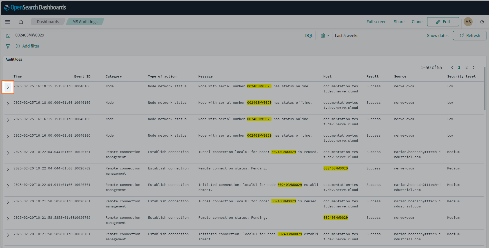
Select › to inspect a log entry to show the full range of all fields. The fields contain the following information:
| Field | Description |
|---|---|
| @timestamp | Timestamps are shown in the format YYYY-MM-DD T hh:mm:ss.sss. The time is taken from the browser's time zone settings. The time zone in which the time stamp was generated is also specified (e.g. UTC+1.00). |
| Additional info | This category is optional. Depending on the event logged, additional information will be displayed here. The information contained in this filed can be used to ease searching for additional logs. Examples of information that could be shown:
|
| Category | This states the area the log applies to. Examples of categories are:
|
| Event ID | An internal code that represents the most important details of a log entry. It consists of:
|
| Host | This shows where the log message originates from. It can be a Management System URL or a node serial number. |
| Message | This is the main information field. It describes the actual event in written text and can contain detailed information like error messages, IDs, image paths and more. Refer to the additional info field if the content of the message field is insufficient. |
| Result | This contains the event result and can be either Success or Fail. |
| Source | This shows the user, process or component that triggered the event. It will show:
|
| Type of action | This field describes the type of event that has occurred. Examples are:
|
| _id | This is a field generated by OpenSearch. It contains a unique identifier that is attached to the log. |
| _index | This is a field generated by OpenSearch. It contains the name of the index that all Management System logs are stored under. |
| _score | This is a field generated by OpenSearch. It is not used for audit logs and will not contain any information. |
| _type | This is a field generated by OpenSearch. It is not used for audit logs and will not contain any information. |
| label | This field shows the label of the log that states the type of log. In the case of audit logs, it will contain audit. |
Event ID code
The Event ID code is an eight-digit number, with every two digits signifying an aspect of the event. Its meaning is generated left to right, meaning that the first digit's pair determines the possible value of the second digit pair and so on. The digits stand for the following:
Event ID code pattern: NNXXYYZZ
|
Take a look at the tables below for possible digits. Keep in mind that the Event ID code is constructed the following way: NN XX YY ZZ.
Refer to the tables below for a list of sources that signify the first two digits NN.
| NN | Source of audit logs |
|---|---|
| 10 | Audit logs for the Management System For more information refer to Logging and monitoring |
| 20 | Audit logs for the node (Description in this section.) |
Refer to the table below for a list of Objects XX and Categories YY.
| XX | Object | YY | Category |
|---|---|---|---|
| 01 | System | 01 | Access control |
| 02 | Reboot | ||
| 03 | Networks | ||
| 04 | Proxy settings | ||
| 05 | Node configuration | ||
| 02 | Workloads | 01 | Workloads deployment |
| 02 | Workload control | ||
| 03 | Remote connections | 01 | Remote connections management |
| 05 | Users | 01 | User management |
| 05 | DNA | 01 | DNA actions |
| 06 | Local repository | 01 | Local repository actions |
| 07 | Docker resources | 01 | Docker resources volumes |
| 02 | Docker resources images |
Refer to the tables below for a list of action that signify the last two digits ZZ.
Note
The Message and Additional info fields in the audit logs dashboard give more context to each event.
Access control (200101ZZ)
The following table shows the events that are logged according to the access control actions.
| ZZ ID | Action | Message | Result |
|---|---|---|---|
| 01 | Login | User <user name> has been logged in successfully. |
Success |
| Invalid credentials. | Fail | ||
| Too many failed requests were made! This account has been temporarily blocked. Please try again later. | Fail | ||
| 02 | Logout | User <user name> has been logged out successfully. |
Success |
| 01 | Logout | Access denied. User does not have permission to access this application. | Fail |
Reboot (200102ZZ)
The following table shows the events that are logged according to the reboot actions.
| ZZ ID | Action | Message | Result |
|---|---|---|---|
| 01 | Reboot | Node reboot started. | Success |
| Reboot action has been initiated from unknown source. | Fail | ||
| Reboot action is not defined in internal configuration file. | Fail | ||
| Reboot action is not allowed. | Fail | ||
| Node reboot started. | Success | ||
| Reboot action has been initiated from unknown source. | Fail | ||
| Reboot action is not defined in internal configuration file. | Fail | ||
| Reboot action is not allowed. | Fail |
Networks (200103ZZ)
The following table shows the events that are logged according to the networks actions.
| ZZ ID | Action | Message | Result |
|---|---|---|---|
| 01 | Networks | Network enabled. | Success |
| Network disabled. | Success | ||
| Invalid network parameter. | Fail | ||
Network is already <data from network>. |
Fail | ||
| 02 | Networks | Network enabled using physical button. | Success |
| Network disabled using physical button. | Success | ||
| 03 | Network config update | Network interfaces were successfully saved. | Success |
| Previous request for network configuration is still in progress! | Fail |
Proxy settings (200104ZZ)
The following table shows the events that are logged according to the proxy settings actions.
| ZZ ID | Action | Message | Result |
|---|---|---|---|
| 01 | Proxy settings | Proxy configuration updated. | Success |
| Values of no_proxy are invalid | Failed |
Node configuration (200105ZZ)
The following table shows the events that are logged according to the node configuration actions.
| ZZ ID | Action | Message | Result |
|---|---|---|---|
| 01 | Configuration update | Configuration updated. | Success |
| 02 | Offboard | Node offboarding started. | Success |
| Node offboarding failed. | Fail | ||
| 03 | SSH password change | SSH password changed. | Success |
| Failed to change system password. | Fail |
Workloads deployment (200201ZZ)
The following table shows the events that are logged according to the workloads deployment actions.
| ZZ ID | Action | Message | Result |
|---|---|---|---|
| 01 | Workload deploy | Workload <workload name and version> and deployment initiated. |
Success |
| 02 | Workload deployment validation | Workload from archive <file name> deployment started. |
Success |
Workload <workload name and version> deployment started. |
Success | ||
Workload <workload name and version> deployment failed. |
Fail | ||
| 03 | Workload deploy | Workload <workload name and version> deployment finished. |
Success |
| 04 | Apply workload configuration | Workload <workload name and version> configuration applied. |
Success |
| 05 | Workload resource update | Workload <workload name and version> resource allocation started. |
Success |
Request to update resource reservation failed: <error message> |
Fail | ||
| 06 | Workload resource update | Workload <workload name and version> resource allocation finished. |
Success |
Failed to finalize resource reservation update for the workload: <error message> |
Fail | ||
Workload <workload name and version> resource allocation finished. |
Success | ||
Failed to finalize resource reservation update for the workload: <error message> |
Fail |
Workload control (200202ZZ)
The following table shows the events that are logged according to the workloads control actions.
| ZZ ID | Action | Message | Result |
|---|---|---|---|
| 01 | Start | Settings of remote connection approval changed. | Success |
| 02 | Stop | The stop action has been initiated for workload <workload name and version>. |
Success |
| 03 | Resume | The resume action has been initiated for workload <workload name and version>. |
Success |
| 04 | Suspend | The suspend action has been initiated for workload <workload name and version>. |
Success |
| 05 | Restart | The start restart has been initiated for workload <workload name and version>. |
Success |
| 06 | Undeploy | The undeploy action has been initiated for workload <workload name and version>. |
Success |
| 07 | Started | Workload <workload name and version> started. |
Success |
| 08 | Stopped | Workload <workload name and version> stopped. |
Success |
| 09 | Suspended | Workload <workload name and version> suspended. |
Success |
| 10 | Undeployed | Workload <workload name and version> undeployed. |
Success |
| 11 | Idle | Workload <workload name and version> idle. |
Success |
| 12 | Error | Workload not found | Fail |
| 13 | Removing failed | Workload not found | Fail |
| 14 | Codesys application downloaded. | Codesys application downloaded. | Success |
Remote connections management (200301ZZ)
The following table shows the events that are logged according to the remote connection management actions. For more information about remote connections refer to Remote connections.
| ZZ ID | Action | Message | Result |
|---|---|---|---|
| 01 | Remote connection settings | Settings of remote connection approval changed. | Success |
| Failed to update remote connection settings. | Fail | ||
| 02 | Remote connection approval | Connection initiation <connection request Uid> has been approved |
Success |
| 03 | Remote connection terminate | Connection removal has been initiated. | Success |
| 04 | Remote connection terminate | Remote connection removed. | Success |
| 05 | Remote connection approval | Remote connection <connection request Uid> approved/rejected |
Success |
| 06 | Remote connection terminate | Remote connection removed. | Success |
User management (200401ZZ)
The following table shows the events that are logged according to the user management actions.
| ZZ ID | Action | Message | Result |
|---|---|---|---|
| 01 | User management | List of users cached on node. | Success |
| Failed to retrieve the users from database. | Fail | ||
| 02 | Delete | Successfully deleted all users. The default admin account has been reactivated. | Success |
| Failed to delete user(s). | Fail | ||
| 03 | Update | Change default admin password successful. | Success |
| The old password you have entered is not correct. | Fail | ||
| 04 | Delete | Successfully deleted all users. The default admin account has been reactivated. | Success |
| Unknown action: delete_all received from MS. | Fail | ||
| 05 | User management | List of users cached on node. | Success |
| Unknown action: get_list received from MS | Fail |
DNA (200501ZZ)
The following table shows the events that are logged according to the DNA actions.
| ZZ ID | Action | Message | Result |
|---|---|---|---|
| 01 | Download target configuration | DNA target configuration downloaded. | Success |
| 02 | Download current configuration | DNA current configuration downloaded. | Success |
| 03 | Re-apply target configuration | DNA reconfiguration initiated, target configuration re-applied. | Success |
| 04 | Cancel target configuration | DNA reconfiguration cancel initiated. | Success |
| 05 | Apply new target configuration | DNA reconfiguration initiated, target configuration applied. | Success |
| 06 | Download target configuration | DNA target configuration downloaded. | Success |
| 07 | Download current configuration | DNA current configuration downloaded. | Success |
| 08 | Re-apply target configuration | DNA reconfiguration initiated, target configuration re-applied. | Success |
| 09 | Cancel target configuration | DNA reconfiguration cancel initiated. | Success |
| 10 | Apply new target configuration | DNA reconfiguration initiated, target configuration applied. | Success |
Local repository (200601ZZ)
The following table shows the events that are logged according to the Local repository actions.
| ZZ ID | Action | Message | Result |
|---|---|---|---|
| 01 | Create repository | The workloads/vm backups mount point: <mount point> has been successfully created. |
Success |
| Mount point not created. Make sure NFS server is running and retry. | Success | ||
| Local repository of this type is already defined | Fail | ||
| 02 | Update repository | The workloads/vm mount point: <mount point> has been successfully updated. |
Success |
| Mount point not created. Make sure NFS server is running and retry. | Success | ||
| Local repository with provided id does not exist. | Fail | ||
| 03 | Delete repository | The workloads/vm mount point: <mount point> has been successfully deleted. |
Success |
| Local repository with provided id does not exist. | Fail | ||
| 04 | Retry repository | The workloads/vm mount point: <mount point> has been successfully retried. |
Success |
| nfs_server_unreachable | Fail |
Docker resources volumes (200701ZZ)
The following table shows the events that are logged according to the Docker resources volumes actions.
| ZZ ID | Action | Message | Result |
|---|---|---|---|
| 01 | List volumes | List of volumes on the node. | Success |
| 02 | Remove volume | Volume removed from the node. | Success |
Volume <volume name> does not exist on the system. |
Fail | ||
Not possible to delete volume: <volume name>. It is being used by containers: <container name> |
Fail | ||
| 03 | List volumes | List of docker volumes on the node. | Success |
| 04 | Remove volume | Successfully deleted volume <volume name> from the node. |
Success |
Docker resources images (200702ZZ)
The following table shows the events that are logged according to the Docker resources images actions.
| ZZ ID | Action | Message | Result |
|---|---|---|---|
| 01 | Remove unused docker images | Removal of docker images not used by any docker container has been initiated. | Success |
| Docker images not used by any docker container have been removed from the system. | Success | ||
| Docker service is not available. | Fail | ||
| 02 | Remove unused docker images | <volume name> initiated removal of all unused Docker images. |
Success |
| Successfully deleted all docker images not used by any docker container. | Success | ||
| Docker service is not available. | Fail |