MFN 100
Deprecated, do not use for new designs.
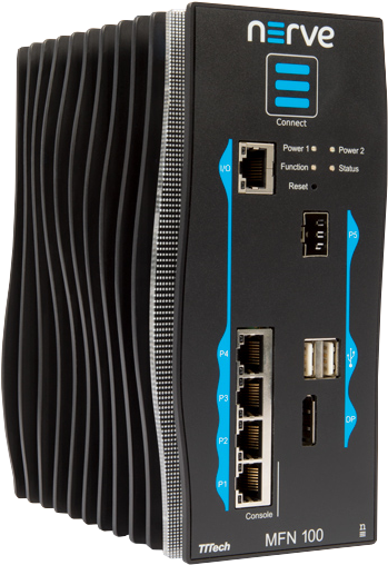
The MFN 100 is a qualified Nerve Device that is optimized and tested for use with Nerve software. The device is designed for use in harsh industrial environments (-40°C to +70°C). It is based on an Intel Atom x5-E3940/50 CPU and offers 4 GB/8 GB RAM and up to 512 GB SSD storage. The MFN 100 offers one I/O port for Ethernet-based fieldbus connectivity, four GbE switch ports and one SFP port. Additional interfaces include two USB 2.0 ports and one DisplayPort.
Hardware information
Find information about the hardware like technical data and physical ports below.
Technical data
| CPU | Intel E3940 4 cores, 1.8 GHz, 4 GB RAM Intel E3950 4 cores, 2.0 GHz, 8 GB RAM |
| Storage | 64 GB SSD MLC 256 GB SSD MLC 512 GB SSD MLC |
| Performance | 1 ms control cycle time achievable with Nerve |
| Interfaces |
|
| Mounting | DIN rail or wall mount |
| Dimensions | (h x w x d): 179 x 87 x 143 mm |
| Weight | 2.1 kg |
| Power | 2 x 24 V redundant input, Average power consumption 12 W |
| Environmental Parameters |
|
| Certificates | CE and UL certified (EN 61000-6-2/4, IEC/UL 61010, CSA C22.2 NO. 61010-1-12) |
Identifying the MFN 100
The label of the MFN 100 can be found on the back of the device, close to the DIN rail clip. Exact identification is possible through the combination of product number (P/N), serial number (S/N) and version number (V/N) that are printed on the label. The model number of the MFN 100 details the variant of the MFN 100:
| Letter or Number | Description |
|---|---|
| CODESYS indicator | This letter indicates whether the device has a CODESYS runtime pre-configured:
|
| SSD size | This number indicates the size of the SSD:
|
| CPU variant | This indicates the CPU variant of the device:
|
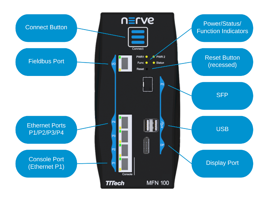
Front panel controls and indicators
Below is an overview of the front panel of the MFN 100, describing physical interfaces, indicators and their labels.
| Label | Description |
|---|---|
| Connect Button | The connect button interrupts the connection on ports P2 to P5 of the MFN 100. This is the behavior in the standard configuration. The function is configurable on request. The button may be configured to change the network configuration. |
| Connection Indicator | The connection indicator is the first fin in the MFN 100 housing. It lights up blue when all required services are initiated and the connection to the Management System is configured. |
| Reset | Holding the button for 4-8 seconds initiates a power cycle. Use a tool with a rounded tip to press the button. |
| Power 1 Power 2 |
Indicators showing power active on the power supply. |
| Status | LED indicating system status
|
| Function | LED indicating CODESYS runtime status
|
| P1 Console | Ethernet port/console port. This port is typically used to connect a workstation to configure the MFN 100. |
| P2/P3/P4 | Ethernet ports |
| P5 | SFP port |
| I/O | Fieldbus interface |
| USB | Two USB 2.0 ports with 1.1 A maximum output current for both ports combined. |
| DP | DisplayPort supporting the DP++ standard. |
Note
P1 to P5 are internally connected to a hardware switch and separated via VLAN tagging. This has two implications.
- Tagged VLAN frames cannot be used to communicate with any entity executed on the MFN 100.
- Do not connect two or more interfaces of the ports P1 to P5 to the same switch (or to the same Ethernet subnet), as this creates a loop.
Power connectors overview
The power connectors are located at the bottom of the MFN 100 next to the label. There are two separate 24 V inputs, two GND inputs and one Functional Earth (FE) input. The inputs are fused internally. The fuse cannot be replaced by the user. The power supply inputs are protected against reverse polarity.
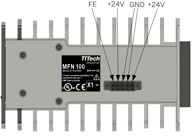
| Pin | Description |
|---|---|
| 1 | Power supply line 2 |
| 2 | GND |
| 3 | GND |
| 4 | Power supply line 1 |
| 5 | Functional Earth (FE) |
Note
The GND and FE pins (pins 2, 3, and 5) are electrically connected to the housing.
Power supply details
| Parameter | Value |
|---|---|
| Operating voltage | 18 - 30 VDC |
| Start-up current | 7 A max. |
| Consumption | 1.4 A continuous 2.1 A peak |
| Dissipated power | 33.6 W at 24 VDC |
Setting up the MFN 100 for Nerve usage
When delivered, Nerve is already installed on the MFN 100. Two network cables and a +24 V DC power supply are required to finish the setup and use Nerve on the MFN 100. This includes connecting the power supply to the mating connector which is delivered with the MFN 100.
- Connect pin 1 of the mating connector to +24 V DC.
- Connect pin 2 of the mating connector to GND.
- Plug the mating connector into the bottom side of the MFN 100.
-
Connect port 2 of the MFN 100 to the internet.
Note
Note that connecting the device to the internet is the best use case, as it enables the easiest way to activate the Nerve license and easy communication with a Management System hosted in the cloud. In general, physical port 2 is used for communication with the Management System over port 443 (HTTPS).
If the MFN 100 does not have internet access and the Management System is hosted on premise, make sure to connect the device to the same network as the Management System.
If neither can be guaranteed, ignore this step until after the node is configured for Management System connection in the Local UI. Also, contact the IT administrator for help on how to allow external devices to connect to the internet or internal network. -
Plug in the power supply.
The MFN 100 will start after a few minutes and light up blue when all necessary services are initiated.
Note
- To connect the MFN 100 to a fieldbus, connect a network cable to the I/O port of the MFN 100 and to a fieldbus interface.
- A second power supply can also be connected to the MFN 100 as a backup. To do so, connect pin 3 of the mating connector to GND and connect pin 4 of the mating connector to +24 V DC.
- When connecting the MFN 100 to the internet through port 2, the device will receive an IP address through DHCP. A static IP address can also be configured but only after the Nerve software license has been activated. The MAC address is located on the device.
Installation and removal on a DIN rail
The MFN 100 is intended for mounting on a DIN rail inside a closed cabinet. Due to its weight it should be installed on a strong DIN rail. No tool is required to install or remove the MFN 100.
Follow these steps to install the MFN 100 on a DIN rail:
- Engage the DIN rail mounting clip of the MFN 100 with the upper edge of the DIN rail.
- Push the MFN 100 down into the DIN rail.
- Place the MFN 100 in a vertical position so that the mounting clip engages the lower edge of the DIN rail.
Follow these steps to remove the MFN 100 from a DIN rail:
- Push the MFN 100 down.
- Rotate the MFN 100 upwards so that the lower edge of the DIN rail disengages.
- Lift the MFN 100 slightly to remove it.
Accessing the Local UI
As Nerve comes pre-installed on the MFN 100, the device can be powered on after setup for product license activation. For that, a connection to the Local UI needs to be established.
- Connect a workstation to port P1.
-
Configure the network adapter of the workstation. The IP address has to be in the range from
172.20.2.5to172.20.2.254with a255.255.255.0subnet mask.Note
Do not use
172.20.2.27for the network adapter IP address. This IP address is used internally by the Nerve system. -
Open a browser window or tab.
- Enter http://172.20.2.1:3333/ to access the Local UI.
At first, only the required elements to activate the Nerve product license are shown in the Local UI. The full extent of the Local UI is unlocked after product license activation and requires a login. For first time log in use the credentials from the customer profile.
Activating the Nerve license
After logging in to the Local UI, the product license can be activated so that Nerve can be used on the device. Make sure that the Local UI can be accessed as described above. License activation can be done either online or offline.
-
Online activation
When the node has internet access, the node will automatically connect to the licensing server. This is the most straightforward way of activating licenses. -
Offline activation
In case of the node not having internet access, the license can be activated with a file-based method. However, note that a workstation with an internet connection is required for connecting to the licensing server in order to upload and download files. This might be the way to activate the license if the Management System is hosted on premise.
Refer to License activation in the user guide for more information and step by step instructions.
Registering the device in the Management System
With the license activated, the node needs to be configured for use in the Management System through the Local UI. Afterwards the node needs to be registered in the Management System.
- Make sure that the Local UI can be accessed as described above.
- Follow this link to connect to the Local UI: http://172.20.2.1:3333/
-
Log in with the credentials from the customer profile.

-
Refer to Node configuration for information on how to configure the device for use in the Management System.
- Refer to Adding a node for information on how to register the node in the Management System.
Additional device specific information
The following information below is device specific information for use with Nerve.
CODESYS related information
For working with the CODESYS Development System, a device description for Nerve Devices is required. The device description can be downloaded from the Nerve Software Center.
The MFN 100 has an Ethernet port that is reserved for machine data acquisition. Connect a network cable to the I/O port of the MFN 100 and to a fieldbus interface to acquire machine data. The CODESYS runtime can be reached at 172.20.2.2.
Physical ports and network interfaces
The table offers a quick overview of the network interfaces that can be reached through the physical ports of the MFN 100.
| Physical port | Network name |
|---|---|
| I/O | io0 |
| P1 | mgmt |
| P2 | wan |
| P3 | extern1 |
| P4 | extern2 |
| P5 | extern3 |
| Notable IP Adresses | |
|---|---|
| Host access | 172.20.2.1 |
| CODESYS runtime access | 172.20.2.2 |
For more information on node internal networking, refer to Node internal networking.
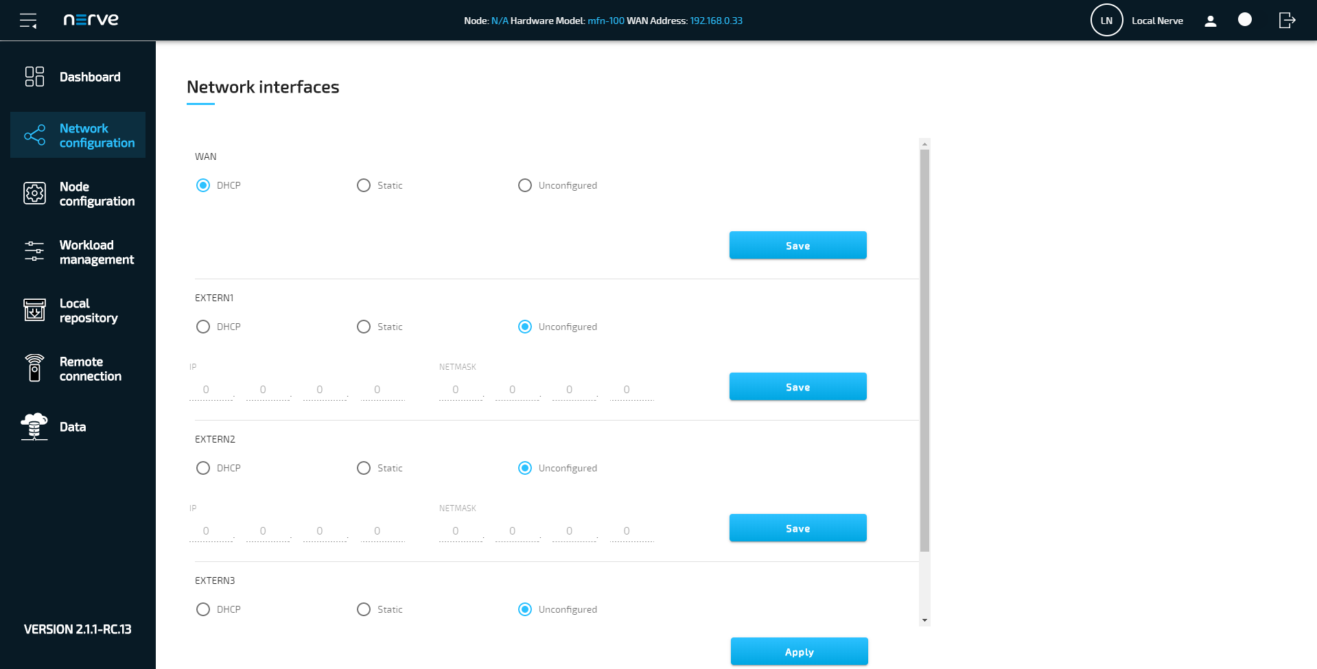
Network configuration
The Ethernet ports of the Nerve Devices can be configured from the Local UI. For the MFN 100, the interfaces in the Local UI represent the physical ports 2, 3, 4 and 5. The console port P1 and the I/O port of the MFN 100 are reserved and cannot be modified. The console port is used solely for configuration purposes. The I/O port is connected to the CODESYS runtime and used for fieldbus communication. Select Network configuration in the navigation on the left to reach this menu.
Manual image installation
In some cases Nerve images need to be installed or updated from a USB drive directly at the Nerve Device.
Refer to the instructions below.
Note that <version_number> and <drivename> are used as a placeholders.
To obtain the correct version number for your device, contact a sales@tttech-industrial.com or submit a request through the TTTech Industrial support portal.
First, here are the requirements for manually installing the Nerve image on the MFN 100:
|
In addition, a workstation is required to prepare the bootable USB drive. Connect the monitor and the keyboard to the MFN 100.
Before beginning with the installation, make sure that the device will boot from the USB drive. Press F7 when the device is booting to enter the boot menu.
- Download the
nerve-node-installer-<version_number>-amd64.img.gzfrom the Nerve Software Center to a workstation. - Extract the
nerve-node-installer-<version_number>-amd64.img.gzfile to retrieve thenerve-node-installer-<version_number>-amd64.img. Depending on the program used, the file might need to be extracted more than once. -
Transfer the extracted
nerve-node-installer-<version_number>-amd64.imgfile to the USB drive using Rufus.Note
Make sure to replace
<version_number>with the version number needed for your device. -
Plug the USB drive into a USB port of the Nerve Device.
- Power on the device.
- Press F7 to enter the boot menu. Make sure that the device will boot from the USB drive.
The setup will start automatically and take a few minutes to complete part 1 of the installation. After a reboot, part 2 of the installation will continue. Once the installation is finished, follow the on screen instructions to either close the installation window or reboot the device. The device will then reach a log in screen, asking for host access log in credentials. Make sure that the device will boot from the hard disk if rebooting the device again.
Note
- In some cases, part 2 of the installation will proceed with a reboot before the installation window can be closed. This is due to certain services needing a device reboot to finish configuration.
- In case of error, the installation window in part 2 will change its background color to red and prompt the user the reinstall from the beginning. In this case, reboot the device and restart the installation from the USB drive.
- Download the
nerve-node-installer-<version_number>-amd64.img.gzfile from the Nerve Software Center. -
Enter the following commands to extract the nerve-node-installer-
-amd64.img.gz` file and transfer the extracted file to the USB drive: tar xf nerve-node-installer-<version_number>-amd64.img.gz sudo dd if=nerve-node-installer-<version_number>-amd64.img bs=4M of=/dev/sd<drivename> status=progress syncNote
Make sure to replace
<drivename>with the system name of the USB drive. Make sure to replace<version_number>with the version number needed for your device. -
Plug the USB drive into a USB port of the Nerve Device.
- Make sure that the device will boot from the USB drive and power on the device.
The setup will start automatically and take a few minutes to complete part 1 of the installation. After a reboot, part 2 of the installation will continue. Once the installation is finished, follow the on screen instructions to either close the installation window or reboot the device. The device will then reach a log in screen, asking for host access log in credentials. Make sure that the device will boot from the hard disk if rebooting the device again.
Note
- In some cases, part 2 of the installation will proceed with a reboot before the installation window can be closed. This is due to certain services needing a device reboot to finish configuration.
- In case of error, the installation window in part 2 will change its background color to red and prompt the user the reinstall from the beginning. In this case, reboot the device and restart the installation from the USB drive.