Skip to content

Provisioning a Virtual Machine workload

Before a Virtual Machine workload can be provisioned, it is required to set up the virtual machine. Virtual Machine workloads can be created on any PC but an environment to effectively create a Virtual Machine workload is not always readily available. Therefore, it is described how the Nerve Device can be utilized to create a Virtual Machine workload. What needs to be done is:

  1. Creating a virtual machine on the node
  2. Installing an operating system on the virtual machine
  3. Obtaining the virtual machine IMG and XML files
  4. Provisioning the Virtual Machine workload in the Management System

In this version, Nerve does not provide a GUI based method for installing an OS on a virtual machine and obtaining the virtual machine IMG and XML configuration files. Therefore, this chapter focuses on the manual process. Three tools are required for the instructions below, assuming Windows is used on the workstation:

  • an X Server application like Xming
  • an SSH client like PuTTY
  • a file transfer client like WinSCP

Also the workstation needs to be connected to the physical port of the Nerve Device associated with host access, and the network adapter IP address of the workstation needs to be configured in the correct range. This information is device specific. Refer to the device guide for information on the Nerve Device.

The instructions below are split up into multiple parts to make them easier to follow. The subsections of the instructions are connected and every subheading is a requirement for the next paragraph.

Note

The virtual machine generated in this chapter is a fresh installation and will be generated on the Nerve Device directly.

Creating a logical volume

Logical volumes are created using the lvcreate command, which takes a number of command-line arguments. Firstly, the -L flag is used to specify the size of the volume. Secondly, the -n flag is used to specify a name for the logical volume. <image_size> and <volume_name> are used as placeholders in the instructions below. The volume group is already predefined with nerve as its name.

  1. Open an SSH client like PuTTY.
  2. Enter the IP address for host access to the Nerve Device under Host Name (or IP address) to log in to the host of the Nerve Device.

    PuTTY Host Login

  3. Log in with the credentials for host access to the Nerve Device.

  4. Enter the following command:

    sudo lvcreate -L <image_size> -n <volume_name> nerve
    

    Creating Logical Volume

Increasing storage in /opt/data and creating a filesystem

The ISO image of the OS needs to be copied to the device from which the virtual machine will be installed. In order to do that, the size of /opt/data needs to be increased. A path to store the ISO file will also be created. <size> is a placeholder for the amount of storage that is added, while nerve/data is the name of the volume group and the logical volume.

  1. Enter the following command to increase storage:

    sudo lvextend -L +<size> -r nerve/data
    

    Increasing storage

  2. Enter the following command to create a filesystem:

    sudo mkfs.ext4 /dev/nerve/<volume_name>
    

    Creating a filesystem

Creating a directory for the ISO file and mounting the filesystem

Create a directory in /opt/data in order to be able to generate the IMG file and XML file that are required for the provisioning of the Virtual machine in the Management System

  1. Enter the following command to create a directory for the ISO file:

    sudo mkdir /opt/data/<directory>
    
  2. Enter the following command to mount the filesystem:

    sudo mount /dev/nerve/<volume_name> /opt/data/<directory>
    

Granting permission for the newly created directory

Take ownership of the new directory in order to be able to work with it, e.g. copying the ISO file into the directory.

Enter the following command to take ownership of the created directory:

sudo chown admin:admin /opt/data/<directory>

Directory and Ownership

Copying the ISO file to the Nerve Device

With the directory created and ownership established, copy the ISO file of the OS to the Nerve Device for the installation on the virtual machine.

Note

The instructions below are hardware specific. The MFN 100 is used as an example in the screenshots. Refer to the device guide for specific information on the Nerve Device.

  1. Open a file transfer client like WinSCP.
  2. Enter the IP address for host access to the Nerve Device under Host Name.
  3. Enter the credentials for host access to the Nerve Device below under User name and Password.

    WinSCP Host Login

  4. Navigate to the /opt/data/<directory> directory on the right side of the WinSCP window. It is located in the root directory.

    WinSCP ISO Folder

  5. Copy the ISO file of the OS that is to be installed on the virtual machine to the directory on the Nerve Device.

Creating a virtual machine on a node

Using the Virtual Machine Manager is recommended to create a virtual machine and install the OS from the ISO file. Note that the virtual machine in this chapter is a fresh installation and will be generated on the Nerve Device directly.

  1. Run Xming or an alternative.
  2. Open an SSH client like PuTTY.
  3. Enter the IP address for host access to the Nerve Device under Host Name (or IP address) to log in to the host of the Nerve Device.

    PuTTY Host Login

  4. Expand Connection > SSH > X11 on the left side.

  5. Tick the checkbox next to Enable X11 forwarding.

    Enable X11 Forwarding

  6. Select Open.

  7. Log in with the credentials for host access to the Nerve Device.
  8. Enter virt-manager.

    Open Virtual Machine Manager

    The interface of the Virtual Machine Manager will open.

    Open Virtual Machine Manager

Inserting the installation file (ISO)

The creation of the virtual machine can now be initiated with the installation of the OS following right after. Note that the Virtual Machine Manager requires the virtual insertion of the ISO file in the beginning while resources for the virtual machine are defined later.

  1. Select File > New Virtual Machine or select the symbol.

    New Virtual Machine

  2. Select Local install media (ISO image or CDROM).

  3. Select Forward.

    Local Install

  4. Select Browse... in the next window.

  5. In the new window select Browse Local.

    Browse Local

  6. Navigate to /opt/data/ by selecting the left arrow next to admin. The opt directory is located in the root directory.

  7. Double-click the directory containing the ISO file.
  8. Select the ISO file of the OS that was copied before.

    ISO Folder

  9. Select Open.

Defining resources for the virtual machine

Next, the amount of memory and the number of CPUs need to be defined, and the logical volume assigned to the virtual machine needs to be selected.

  1. Select Forward.

    Forward

  2. Define how much memory and how many CPUs to assign to this virtual machine.

  3. Select Forward.

    Memory and CPU

  4. Select Select or create custom storage.

  5. Select Manage....

    Custom Storage

Installing the operating system

Now the virtual machine will be initiated and the installation of the OS will be started.

  1. Select the pool that was created in the command line on the left side in the Choose Storage Volume window. Make sure it is the volume with the location opt/data/.
  2. Select the plus symbol in the middle of the screen.

    Choose Volume

  3. Enter a name for the IMG file.

    Name IMG

    Note

    Make sure that the value entered for Max Capacity is a factor of 512 Bytes. Any value that is not a factor of 512 B will cause an error when the virtual machine workload is deployed. In other words, do not enter any decimal value except .0 or .5.

  4. Select Finish.

  5. Select the IMG file from the list in the middle.
  6. Select Choose Volume.

    Choose IMG

  7. Select Forward to initialize the installation of the OS on the virtual machine.

    Choose Volume

  8. Enter a name for the virtual machine.

  9. Select Finish. The virtual machine will be initiated and the installation of the OS will be started.

    Initiate Installation

  10. Complete the installation of the OS. Follow the instructions provided by the vendor.

  11. After the installation is completed, right-click the virtual machine in the main Virtual Machine Manager window.
  12. Select Shut Down > Shut Down to shut down the VM.

    Shut Down VM

Defining network interfaces

In order for the VM to communicate with the Nerve network, it needs network interfaces. While these are defined when provisioning the VM workload in the Management System, the VM itself needs to have "network cards" installed that represent these interfaces. This means that the purpose of the VM and its interfaces, the number of interfaces and the Nerve networks that will be connected to them need to be known before attempting the following instructions. Note that this step also requires a user with knowledge about the VM, as it requires configuration inside of the VM.

  1. Right-click the virtual machine in the main Virtual Machine Manager window.
  2. Select Open to open the control window.

    Open VM control window

  3. Select the light bulb symbol in the toolbar to display hardware details.

    Open hardware details

  4. Select Add Hardware in the lower-left.

    Add hardware

  5. Select Network in the list.

    Select Network

  6. Configure the Network source the following way depending on the desired interface. Refer to Networks for Virtual Machine workloads for more information on the interfaces.

    Interface Action
    mgmt
    1. Select Specify shared device name from the drop-down menu
    2. Enter mgmt in the Bridge name: field.
    3. Select Finish to add the network card.
    wan
    1. Select Specify shared device name from the drop-down menu .
    2. Enter wan in the Bridge name: field.
    3. Select Finish to add the network card.
    extern1
    1. Select Specify shared device name from the drop-down menu .
    2. Enter extern1 in the Bridge name: field.
    3. Select Finish to add the network card.
    extern2
    1. Select Specify shared device name from the drop-down menu .
    2. Enter extern2 in the Bridge name: field.
    3. Select Finish to add the network card.
    extern3
    1. Select Specify shared device name from the drop-down menu .
    2. Enter extern3 in the Bridge name: field.
    3. Select Finish to add the network card.
    default
    1. Select Virtual network 'default' : NAT from the drop-down menu.
    2. Select Finish to add the network card.
    extern1-nat
    1. Select Virtual network 'extern1-nat' : NAT to extern1 from the drop-down menu.
    2. Select Finish to add the network card.
    extern2-nat
    1. Select Virtual network 'extern2-nat' : NAT to extern2 from the drop-down menu.
    2. Select Finish to add the network card.
    extern3-nat
    1. Select Virtual network 'extern3-nat' : NAT to extern3 from the drop-down menu.
    2. Select Finish to add the network card.
    rtvm
    1. Select Specify shared device name from the drop-down menu .
    2. Enter br-rtvm in the Bridge name: field.
    3. Select Finish to add the network card.
    isolated1
    1. Select Specify shared device name from the drop-down menu
    2. Enter br-isolated1 in the Bridge name: field.
    3. Select Finish to add the network card.
    isolated2
    1. Select Specify shared device name from the drop-down menu .
    2. Enter br-isolated2 in the Bridge name: field.
    3. Select Finish to add the network card.
    isolated3
    1. Select Specify shared device name from the drop-down menu .
    2. Enter br-isolated3 in the Bridge name: field.
    3. Select Finish to add the network card.
    isolated4
    1. Select Specify shared device name from the drop-down menu .
    2. Enter br-isolated4 in the Bridge name: field.
    3. Select Finish to add the network card.
    isolated5
    1. Select Specify shared device name from the drop-down menu .
    2. Enter br-isolated5 in the Bridge name: field.
    3. Select Finish to add the network card.

    Note

    The device model can be ignored, as the Management System will set the required parameters once the VM is provisioned as a workload.

  7. Repeat steps 4 to 6 until all desired interfaces have been defined.

    Note

    Note that one virtual network card is defined by default when creating the virtual machine. The Network source is set to Virtual network 'default' : NAT so that the VM can have internet access through the default network. Remove or modify this network card if internet access for the VM is not desired.

  8. Select the play symbol to launch the virtual machine.

The virtual machine is being launched because further configuration steps need to be taken inside of the VM. The IP addresses of the network cards that were defined above need to be configured (static or dynamic). This step requires a user with knowledge about the VM, as it requires configuration inside of the VM. Refer to Networks for Virtual Machine workloads for more information on the interfaces and their IP ranges.

Copying the IMG file to a local workstation

With the generation of the VM, the IMG file of the VM has also been generated on the Nerve Device. Copy the IMG file to the local workstation.

  1. Right-click the virtual machine in the main Virtual Machine Manager window.
  2. Select Shut Down > Shut Down to shut down the VM.

    Shut Down VM

  3. Switch to the SSH client window.

  4. Enter the following command:

    sudo chmod o+r /opt/data/<directory>/<vmname>.img
    

    Note

    The IMG file is called <vmname>.img in the command example above. Replace the placeholder name of the image in the command with the actual name of the IMG file.

  5. Open a file transfer client like WinSCP.

  6. Enter the IP address for host access to the Nerve Device under Host Name.
  7. Enter the credentials for host access to the Nerve Device below under User name and Password.

    WinSCP Host Login

  8. Navigate to /opt/data/<directory> on the right side of the window. The opt directory is located in the root directory.

  9. Copy the <vmname>.img file to the local workstation.

    Copy IMG File

The virtual machine has now been generated on the Nerve Device and the IMG file of the virtual machine is now on the local workstation.

Note

  • To use the Virtual machine snapshots feature, the IMG or RAW file of the VM needs to be converted to the QCOW2 format. Use the converted QCOW2 file as the image file when provisioning the workload in the Management System. A tool that can be used is qemu-img on Linux for example.
  • However, note that Virtual machine workloads using QCOW2 images cannot be deployed to nodes running on XEN hypervisor.
  • Do not deploy the virtual machine from the process above to the same Nerve Device through the Management System. The virtual machine will be present twice. The deployment of the virtual machine from the process above should be done to different nodes.

Obtaining the XML file

When the IMG file was generated on the Nerve Device, an XML file for the IMG file was generated as well. It also has to be obtained manually. However, before it can be copied to the workstation. It has to be transferred out of the etc directory.

  1. Switch to the SSH client window.
  2. Navigate to /opt/data/<directory> by entering the following command:

    cd ../../opt/data/<directory>
    
  3. Enter the following command to dump the XML file into the directory:

    virsh dumpxml <volume_name> > <filename>.xml
    

    Dump XML

  4. Enter the following command:

    sudo chmod o+r /opt/data/<directory>/<filename>.xml  
    

    Note

    Replace the placeholder name of the XML file in the command with the actual name of the XML file. The XML file is called vm.xml in the following screenshots below.

  5. Open a file transfer client like WinSCP.

  6. Enter the IP address for host access to the Nerve Device under Host Name.
  7. Enter the credentials for host access to the Nerve Device below under User name and Password.

    WinSCP Host Login

  8. Navigate to /opt/data/<directory> on the right side of the window. The opt directory is located in the root directory.

  9. Copy the <filename>.xml file to the local workstation.

    Copy XML File

With this all the necessary files to provision a Virtual Machine workload for this virtual machine are ready.

Provisioning a Virtual Machine workload

The following instructions only cover the required settings for provisioning a Virtual Machine workload. Optional settings will be left out. Extended options are addressed in the last section of this chapter. However, note that some of these settings are necessary to provision a functioning workload. Make sure to understand the workload and its purpose before provisioning a workload.

Other workload types that can be provisioned are:

The process for each workload is highlighted in its respective chapter.

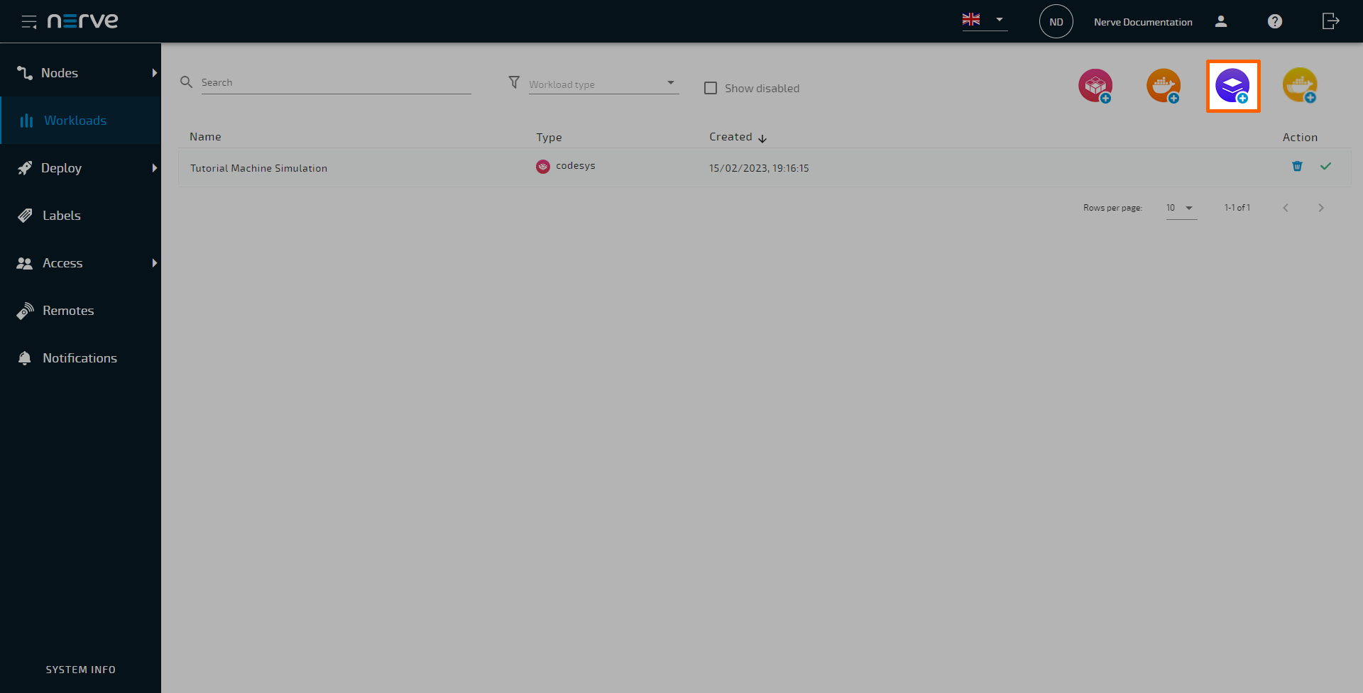
  1. Log in to the Management System.
  2. Select Workloads in the navigation on the left.
  3. Select the virtual machine symbol (Add new VM workload) in the upper-right.

    Virtual Machine Workload

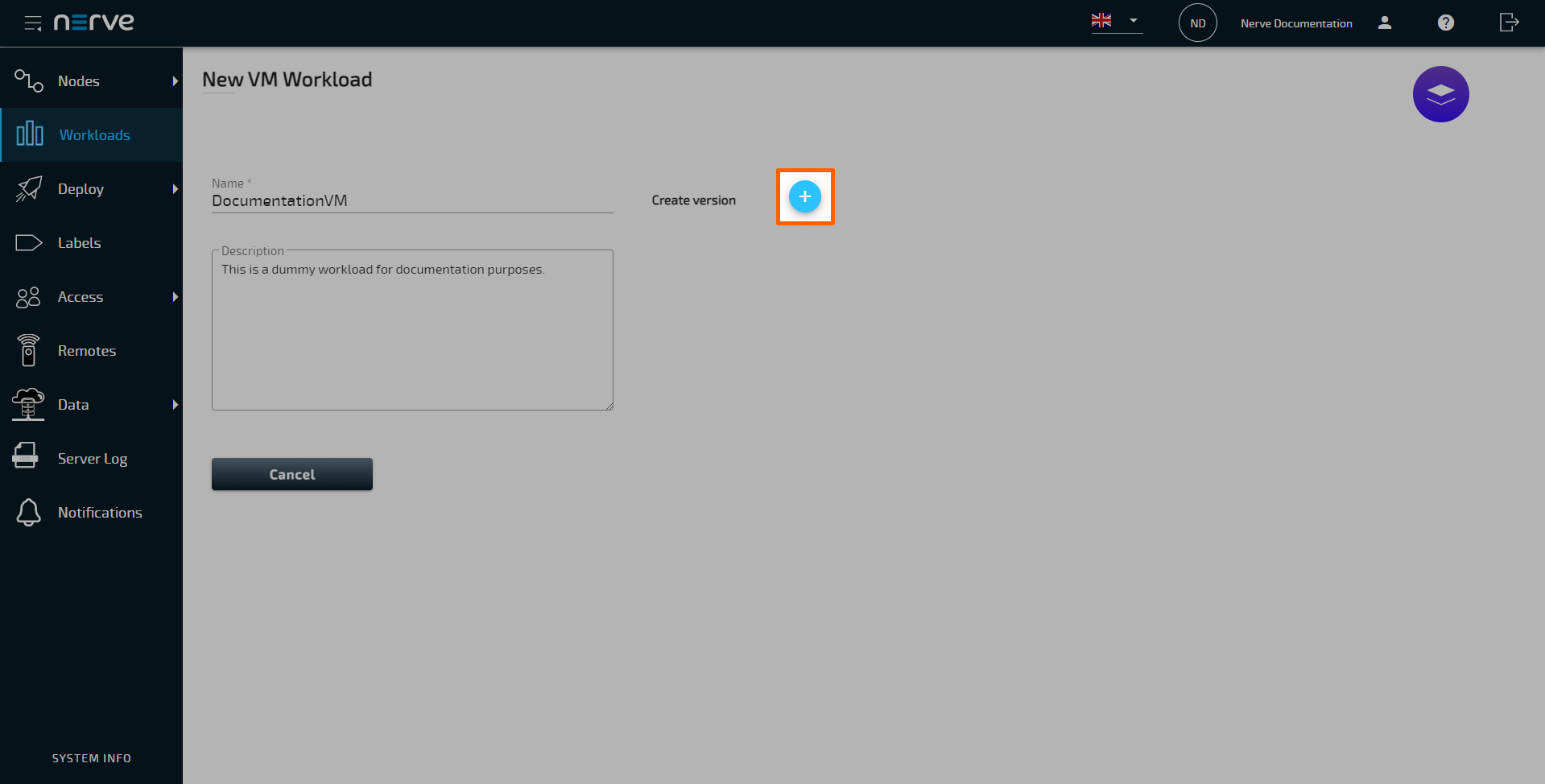
  4. In the new window, enter a name for the workload.

  5. Select the plus symbol next to Create versions to add a new version of the workload.

    New Version

  6. In the next window, enter the following information in the Basic tab:

    Category Settings and descriptions
    VERSION SPECIFIC INFO Version name
    Enter a name for the version of this workload.

    Release name
    Enter a Release name for the version of this workload.
    VIRTUAL MACHINE FILES TO UPLOAD Virtual machine image
    Select the upward arrow symbol here to add the virtual machine image. The image has to be a QCOW2, IMG or RAW file. In case of a large file, the virtual machine image can also be compressed and uploaded as a GZIP or ZIP file.
    Note that the Virtual machine snapshots feature is only available when using a QCOW2 image. Convert IMG or RAW files to the QCOW2 format first before uploading.

    Virtual machine xml
    Select the upward arrow symbol here to add the virtual machine XML file.
    RESOURCES Number of virtual CPUs
    Enter the number of virtual CPUs to use for this virtual machine. This setting can be changed again after the deployment of the workload.

    Limit memory to
    Assign how much system memory the workload is allowed to use. This setting can be changed again after the deployment of the workload.

    Version Settings

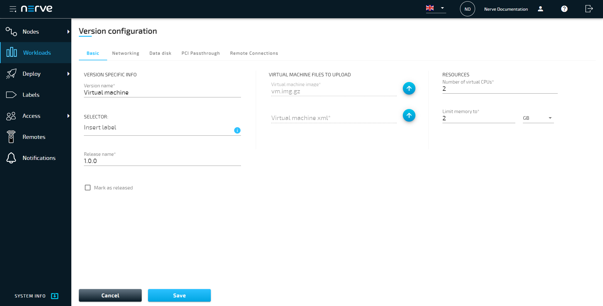
  7. Select the Networking tab.

  8. Select the plus symbol to add a new interface.
  9. Select Bridged or NAT from the drop-down menu.
  10. Enter the interface name in the Interface field.
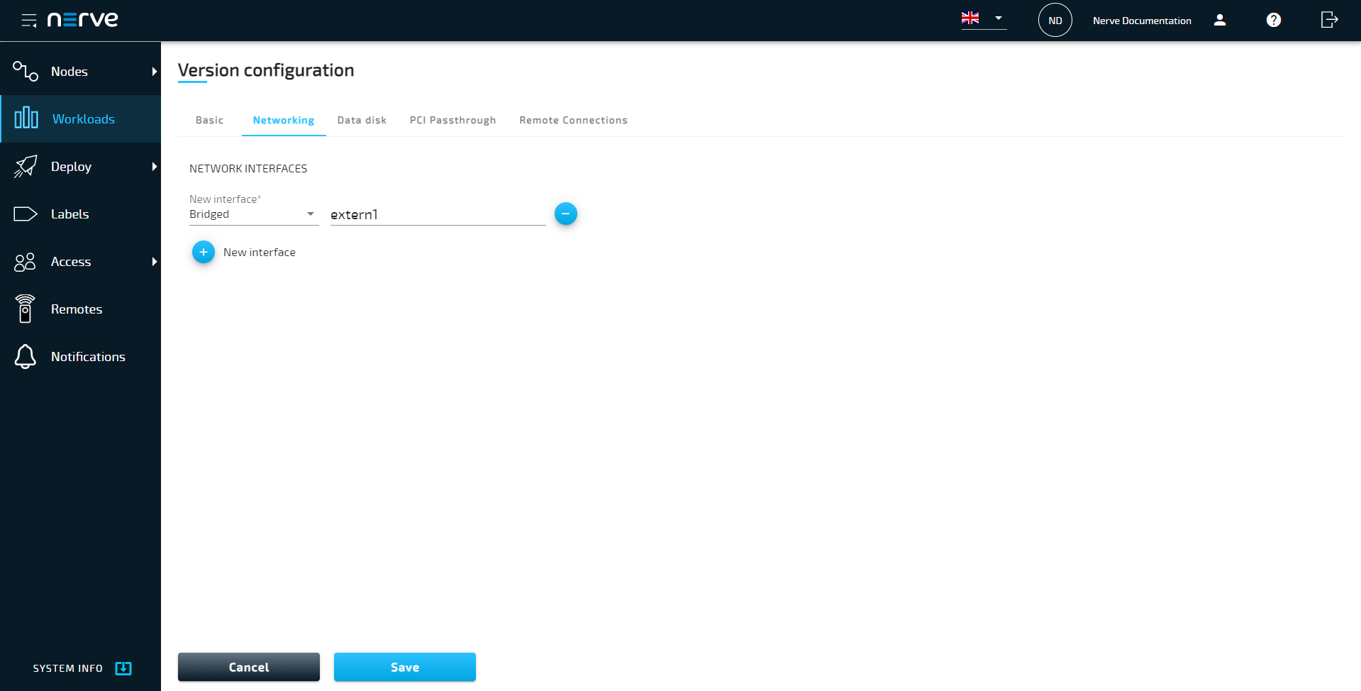
    New interface

    Note

    Repeat this process to add the same number and type of interfaces in the same order as they were added as network cards in Defining network interfaces above.

  11. Select Save in the lower-left corner to save the workload version.

The workload has now been provisioned and is ready to be deployed in the Deploy menu. For more information on how to control the workload after deployment and use workload specific features, refer to Workload control.

Note

  • Note that Virtual machine workloads using QCOW2 images cannot be deployed to nodes running on XEN hypervisor.
  • While some settings are not required to provision a Virtual Machine workload in the Management System, additional settings will have to be filled in for the workload to perform as desired. Depending on the virtual machine that will be deployed, new interfaces might have to be defined. Keep this in mind and make sure to learn the details about the virtual machine.

Settings for Virtual Machine workloads

In the instructions above, all optional settings have been left out. Below is an overview of all the options with an explanation to each option.

Basic tab

Category Settings and descriptions
VERSION SPECIFIC INFO Name
A name for the workload version. This could be a reminder for a certain configuration.
Example: Unlimited as a name for a virtual machine that has unlimited access to CPU resources.

SELECTOR
If labels have been defined and assigned to nodes, add them as selectors to the workload. When deploying a workload, the list of nodes will be filtered automatically to the specified label. Select the Insert label field to see a list of available labels.

Release name
A release name for the workload version. This could be a version number. Example: 1.0.1

Mark as released
Tick this checkbox to mark this workload as released. Once marked as released, the workload cannot be edited anymore.
VIRTUAL MACHINE FILES TO UPLOAD Virtual machine image
Upload the virtual machine image with the file extension QCOW2, RAW or IMG here. Do this by selecting the upward arrow symbol and selecting the file in the file browser. This is the first file generated in the process before. In case of a large file, the virtual machine image can also be compressed and uploaded as a GZIP or ZIP file.
Note that the Virtual machine snapshots feature is only available when using a QCOW2 image. Convert IMG or RAW files to the QCOW2 format first before uploading. However, note that Virtual machine workloads using QCOW2 images cannot be deployed to nodes running on XEN hypervisor.

Virtual machine xml
Upload the virtual machine XML file here. Do this by selecting the upward arrow symbol and selecting the file in the file browser. This is the second file generated in the process before.

Note that the settings defined under Virtual machine specific info are going to overwrite parts of this XML file.

Enable snapshot
Tick the checkbox to enable the Virtual machine snapshots feature. Note that this is only available if a QCOW2 image is uploaded (uncompressed or zipped). In addition, the active user needs to have the appropriate permissions assigned for the snapshot command to appear in the workload control screen. However, note that Virtual machine workloads using QCOW2 images cannot be deployed to nodes running on XEN hypervisor.
Once the criteria are met and the checkbox is ticked, a field labeled Additional disk space appears. Define the disk space here that will be reserved for the VM snapshot. The additional disk space depends on the defined memory for the VM, the VM disk size and should also include about 3% of overhead. Also, keep in mind the duration of how long the snapshot will be kept. The longer a snapshot is kept, the larger it will grow, requiring a larger amount of additional disk space. It is not recommended to keep a snapshot for a long time. In that case, consider creating a backup instead.
RESOURCES Number of virtual CPUs
Define the number of virtual CPUs to assign to this virtual machine. The CPUs are then reserved exclusively for the Virtual Machine workload and cannot be used by other processes. This setting is mandatory and the workload cannot be provisioned if it is left blank. Note that this setting can be changed again after the deployment of the workload without having to undeploy and redeploy the workload. Refer to Changing resource allocation of a deployed Virtual Machine workload for more information.

Limit memory to
Assign how much system memory the workload is allowed to use.
The memory assigned here will be reserved exclusively for this Virtual Machine workload and will not be available for any other processes. This setting is mandatory and the workload cannot be provisioned if it is left blank. Note that this setting can be changed again after the deployment of the workload without having to undeploy and redeploy the workload. Refer to Changing resource allocation of a deployed Virtual Machine workload for more information.

Networking tab

Category Settings and descriptions
NETWORK INTERFACES Select the plus symbol to add a new interface. Choose between a bridged interface and a NAT-interface. For NAT-interfaces port mappings for TCP and UDP can be defined. Also, remember to add the same number and type of interfaces in the same order as they were added as network cards in Defining network interfaces above. If the Virtual Machine workload is defined without any network interfaces, the networks from the network cards defined in Defining network interfaces above are taken by the system automatically.

The names of the interfaces here have to match the names of the pre-defined network interfaces. Also, make sure to not use reserved ports for the workload. Refer to the networking chapter for more detailed information.

Data disk tab

Category Settings and descriptions
DATA DISK Select the plus symbol to add a new data disk for the virtual machine. This data disk functions like an extra hard drive for data outside of the virtual machine. Enter a Data disk name and define the Disk size.

PCI Passthrough tab

Category Settings and descriptions
PCI PASSTHROUGH This is a setting that should only be used by users with expert knowledge. Select the plus symbol to add a PCI passthrough to the virtual machine. However, note that only a certain types of device can be used:Enter the PCI address of the interface to pass through to be directly used by the virtual machine. Note that the PCIe address is specific to a certain hardware. When using this option, the nodes running on this specific hardware should be limited by using selectors. Refer to the labels chapter for more information on selectors.

Remote connections tab

Category Settings and descriptions
REMOTE CONNECTIONS Select the Remote connections tab to configure a remote connection to the workload. Make sure to configure the workload first so that a remote connection can be established.

Refer to Remote connections for more information and instructions for all remote connection types.