MFN 200
The MFN 200 is an industrial PC optimized and tested for use with Nerve software, for a variety of industry 4.0 applications such as collecting data from industrial processes and machines; storing, analyzing and transferring data and executing applications among others. It is specifically designed for industrial applications.
Nerve software comes pre-installed when purchasing an MFN 200.
Hardware information
Find information about the hardware like technical data and physical ports below.
MFN 200 variants
The variants of the MFN 200 come with different RAM and SSD sizes. Currently available variants that are covered by this document include:
| Product name | Part number | Memory and storage | Version |
|---|---|---|---|
| MFN 200 08-128 | 14682 | 8 GB RAM and 128 GB storage | 1.0.0 |
| MFN 200 16-256 | 14671 | 16 GB RAM and 256 GB storage | 1.0.0 |
Technical data
The table contains the technical data of both MFN 200 variants where applicable.
| CPU | MFN 200 08-128 Intel® Atom® x6414RE, 4 cores, 1.5 GHz, TCC MFN 200 16-256 Intel® Atom® x6425RE, 4 cores, 1.9 GHz, TCC |
| Memory | MFN 200 08-128 8 GB RAM MFN 200 16-256 16 GB RAM |
| Storage | MFN 200 08-128 128 GB SSD MFN 200 16-256 256 GB SSD |
| Interfaces |
|
| Mounting | DIN rail or wall mount |
| Dimensions | 100 mm (L) x 100 mm (W) x 95 mm (H) |
| Weight | 0.79 kg with DIN rail 0.78 kg without DIN rail |
| Power | 24 V DC |
| Environmental parameters |
|
| Certificates | CE (Declaration of conformity) RoHS |
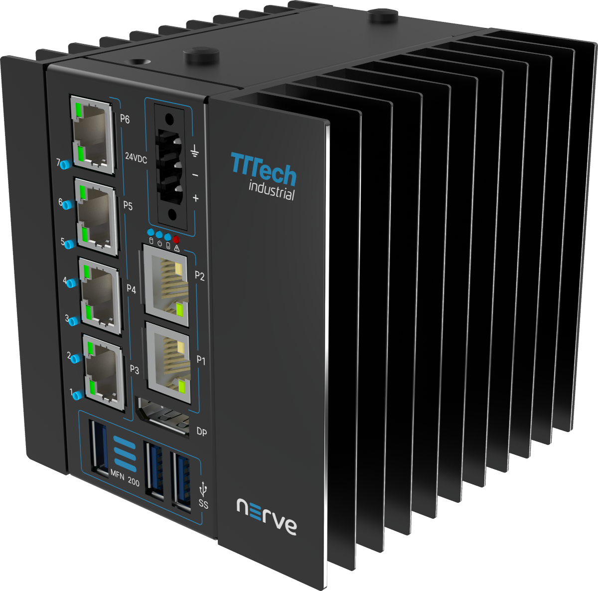
Front panel and indicators
Below is an overview of the front panel of the MFN 200, describing physical interfaces, indicators and their labels.
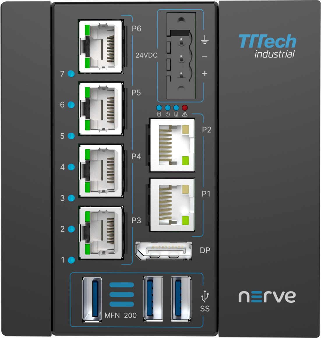
| Label | Description |
|---|---|
| 24 VDC | 9 to 36 VDC with chassis GND |
| Status indicator LEDs | The LEDs from left to right are:
|
| P1 | io0. This port is typically used to connect to the fieldbus. |
| P2 | wan. This port is typically used to connect to the Internet. |
| P3 | Console port. This port is typically used to connect a computer for configuration. |
| P4/P5/P6 | Ethernet ports |
| DP | Display Port |
| SS | Three USB 3.2 ports |
| LED 1 | LED indicating system status
|
| LED 2 | LED indicating CODESYS runtime status
|
| LED 3 | LED indicating the connection status.
|
| LED 4 to 7 | Not in use. |
Power supply
The power supply connectors are located on the front panel of the MFN 200. A 3-position, screw-type terminal block (MC 1,5/ 2-STF-3,5) is provided for connecting power to the terminal.
| Pin | Description |
|---|---|
| ⏚ | Chassis GND |
| – | GND |
| + | 9 to 36 VDC |
Setting up the MFN 200 for Nerve usage
When delivered, Nerve is already installed on the MFN 200. Two network cables and a +24 V DC power supply are required to finish the setup and use Nerve on the MFN 200.
- Plug the terminal block into the bottom side of the MFN 200.
-
Connect P2 of the MFN 200 to the internet.
Note
Note that connecting the device to the internet is the best use case, as it enables the easiest way to activate the Nerve license and easy communication with a Management System hosted in the cloud. In general, P2 is used for communication with the Management System over port 443 (HTTPS).
If the MFN 200 does not have internet access and the Management System is hosted on premise, make sure to connect the device to the same network as the Management System.
If neither can be guaranteed, ignore this step until after the node is configured for Management System connection in the Local UI. Also, contact the IT administrator for help on how to allow external devices to connect to the internet or internal network. -
Plug in the power supply.
The MFN 200 will start after a few minutes.
Note
- To connect the MFN 200 to a fieldbus, connect a network cable to P1 of the MFN 200 and to a fieldbus interface.
- When connecting the MFN 200 to the internet through P2, the device will receive an IP address through DHCP. A static IP address can also be configured but only after the Nerve software license has been activated. The MAC address is located on the device.
Installation and removal on a DIN rail
The MFN 200 is intended to be mounted on a 35 mm (W), 7.5 mm(H) DIN rail inside a closed cabinet. Before mounting, the DIN rail needs to be applied to the MFN 200. Fasten the DIN rail bracket with M3 x 5L screws. It is advisable to install a strong DIN rail. No tool is required to install or remove the MFN 200.
Follow these steps to install the MFN 200 on a DIN rail:
- Make sure that the DIN rail is fastened to the MFN 200.
- Engage the DIN rail mounting clip of the MFN 200 with the upper edge of the DIN rail.
- Push the MFN 200 down into the DIN rail.
- Place the MFN 200 in a vertical position so that the mounting clip engages the lower edge of the DIN rail.
Follow these steps to remove the MFN 200 from a DIN rail:
- Push the MFN 200 down to un-secure the device on the rail.
- Rotate the MFN 200 upwards so that the lower edge of the DIN rail disengages.
- Lift the MFN 200 slightly to remove it.
Accessing the Local UI
As Nerve comes pre-installed on the MFN 200, the device can be powered on after setup for product license activation. For that, a connection to the Local UI needs to be established.
- Connect a workstation to port P3.
-
Configure the network adapter of the workstation. The IP address has to be in the range from
172.20.2.5to172.20.2.254with a255.255.255.0subnet mask.Note
Do not use
172.20.2.27for the network adapter IP address. This IP address is used internally by the Nerve system. -
Open a browser window or tab.
- Enter http://172.20.2.1:3333/ to access the Local UI.
At first, only the required elements to activate the Nerve product license are shown in the Local UI. The full extent of the Local UI is unlocked after product license activation and requires a login. For first time login, use the credentials from the customer profile.
Activating the Nerve license
After logging in to the Local UI, the product license can be activated so that Nerve can be used on the device. Make sure that the Local UI can be accessed as described above. License activation can be done either online or offline.
-
Online activation
When the node has internet access, the node will automatically connect to the licensing server. This is the most straightforward way of activating licenses. -
Offline activation
In case of the node not having internet access, the license can be activated with a file-based method. However, note that a workstation with an internet connection is required for connecting to the licensing server in order to upload and download files. This might be the way to activate the license if the Management System is hosted on premise.
Refer to License activation in the user guide for more information and step by step instructions.
Registering the device in the Management System
With the license activated, the node needs to be configured for use in the Management System through the Local UI. Afterwards the node needs to be registered in the Management System.
- Make sure that the Local UI can be accessed as described above.
- Follow this link to connect to the Local UI: http://172.20.2.1:3333/
-
Log in with the credentials from the customer profile.

-
Refer to Node configuration for information on how to configure the device for use in the Management System.
- Refer to Adding a node for information on how to register the node in the Management System.
Additional device specific information
The following information below is device specific information for use with Nerve.
CODESYS related information
For working with the CODESYS Development System, a device description for Nerve Devices is required. The device description can be downloaded from the Nerve Software Center.
The MFN 200 has an Ethernet port that is reserved for machine data acquisition. Connect a network cable to P1 of the MFN 200 and to a fieldbus interface to acquire machine data. The CODESYS runtime can be reached at 172.20.2.2.
Physical ports and network interfaces
The table offers a quick overview of the network interfaces that can be reached through the physical ports of the MFN 200.
| Physical port | Network name |
|---|---|
| P1 | io0 |
| P2 | wan |
| P3 | mgmt |
| P4 | extern1 |
| P5 | extern2 |
| P6 | extern3 |
For more information on node internal networking, refer to Node internal networking.
Manual image installation
In some cases, Nerve images need to be installed or updated directly on the Nerve Device using a USB drive.
Follow the instructions below.
Note that <version_number> and <drivename> are used as a placeholders.
To obtain the correct version number for your device, contact a sales@tttech-industrial.com or submit a request through the TTTech Industrial support portal.
Below is a list of items required to manually install the Nerve image on the MFN 200:
|
In addition, a workstation is required to prepare the bootable USB drive. Connect the monitor and the keyboard to the MFN 200.
Before beginning with the installation, make sure that the device will boot from the USB drive. Press F7 when the device is booting to enter the boot menu.
- Download the
Nnerve-node-installer-<version_number>-amd64.img.gzfrom the Nerve Software Center to a workstation. - Extract the
nerve-node-installer-<version_number>-amd64.img.gzfile to retrieve thenerve-node-installer-<version_number>-amd64.img. Depending on the program used, the file might need to be extracted more than once. -
Transfer the extracted
nerve-node-installer-<version_number>-amd64.imgfile to the USB drive using Rufus.Note
Make sure to replace
<version_number>with the version number needed for your device. -
Plug the USB drive into a USB port of the Nerve Device.
- Power on the device.
- Press F7 to enter the boot menu. Make sure that the device will boot from the USB drive.
The setup will start automatically and take a few minutes to complete part 1 of the installation. After a reboot, part 2 of the installation will continue. Once the installation is finished, follow the on screen instructions to either close the installation window or reboot the device. The device will then reach a log in screen, asking for host access log in credentials. Make sure that the device will boot from the hard disk if rebooting the device again.
Note
- In some cases, part 2 of the installation will proceed with a reboot before the installation window can be closed. This is due to certain services needing a device reboot to finish configuration.
- In case of error, the installation window in part 2 will change its background color to red and prompt the user the reinstall from the beginning. In this case, reboot the device and restart the installation from the USB drive.
- Download the
nerve-node-installer-<version_number>-amd64.img.gzfile from the Nerve Software Center. -
Enter the following commands to extract the
nerve-node-installer-<version_number>-amd64.img.gzfile and transfer the extracted file to the USB drive:tar xf nerve-node-installer-<version_number>-amd64.img.gz sudo dd if=nerve-node-installer-<version_number>-amd64.img bs=4M of=/dev/sd<drivename> status=progress syncNote
Make sure to replace
<drivename>with the system name of the USB drive. Make sure to replace<version_number>with the version number needed for your device. -
Plug the USB drive into a USB port of the Nerve Device.
- Make sure that the device will boot from the USB drive and power on the device.
The setup will start automatically and take a few minutes to complete part 1 of the installation. After a reboot, part 2 of the installation will continue. Once the installation is finished, follow the on screen instructions to either close the installation window or reboot the device. The device will then reach a log in screen, asking for host access log in credentials. Make sure that the device will boot from the hard disk if rebooting the device again.
Note
- In some cases, part 2 of the installation will proceed with a reboot before the installation window can be closed. This is due to certain services needing a device reboot to finish configuration.
- In case of error, the installation window in part 2 will change its background color to red and prompt the user the reinstall from the beginning. In this case, reboot the device and restart the installation from the USB drive.
User and installation guide PDF
Download the MFN 200 user and installation guide PDF for a document containing technical data, installation instructions and other information about the MFN 200.
Declaration of conformity
![]()
This device is in conformity with the requirement of the following EU legislations and harmonized standards: EN61000-6-4, Class A, EN61000-6-2. It also complies with the Council direction. Download the declaration of conformity here.