Workload control
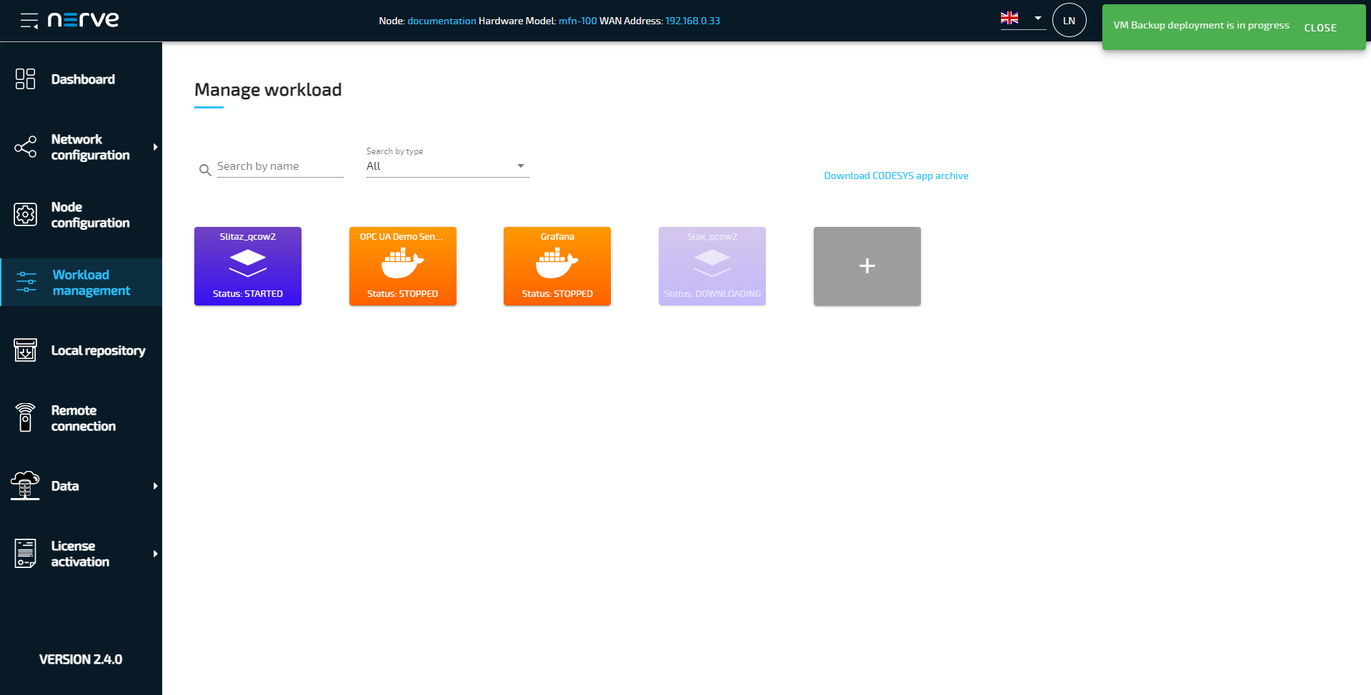
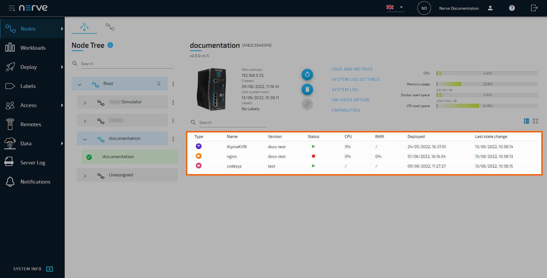
In the Management System, workloads are located below the node details in the node tree. In the Local UI, they can be found in the Workload management menu. Selecting a workload allows control of the respective workload. There are unique additional control options for each workload type. Note that CODESYS workloads can only be controlled from the Local UI.

| Item | Description |
|---|---|
| Back button (1) | Select this to return to the node tree. |
| Status indicator (2) | The symbol here indicates the status of the workload:
|
| Workload and device name (3) | The names of the workload, version and the device are displayed here as: <workloadname> [<versionname>] Node: <devicename> Selecting the workload name here redirects to the workload version settings of this workload. Note that due to compatibility reasons, the release name is displayed instead of the version name for nodes older than 2.5.0. |
| Tabs (4) | Information and control options for the deployed workload are structured into tabs. The default tabs are: Control This tab is the default view, containing the control panel, resource graphs, some workload specific features and more. Logs This tab has two sections. In the section Workload activity you see log messages describing the activity of the workload since its deployment. The latest log message is at the top of the message window. Logs are displayed with the following information:
 to download the activity log of this workload as a CSV file. However, note that the downloaded file has a limit of 10.000 characters. to download the activity log of this workload as a CSV file. However, note that the downloaded file has a limit of 10.000 characters. Select the outgoing link icon  to open audit logs on Open Search filtered for this workload. to open audit logs on Open Search filtered for this workload.Select the refresh icon  to load the latest workload activities for this workload in the message window. to load the latest workload activities for this workload in the message window.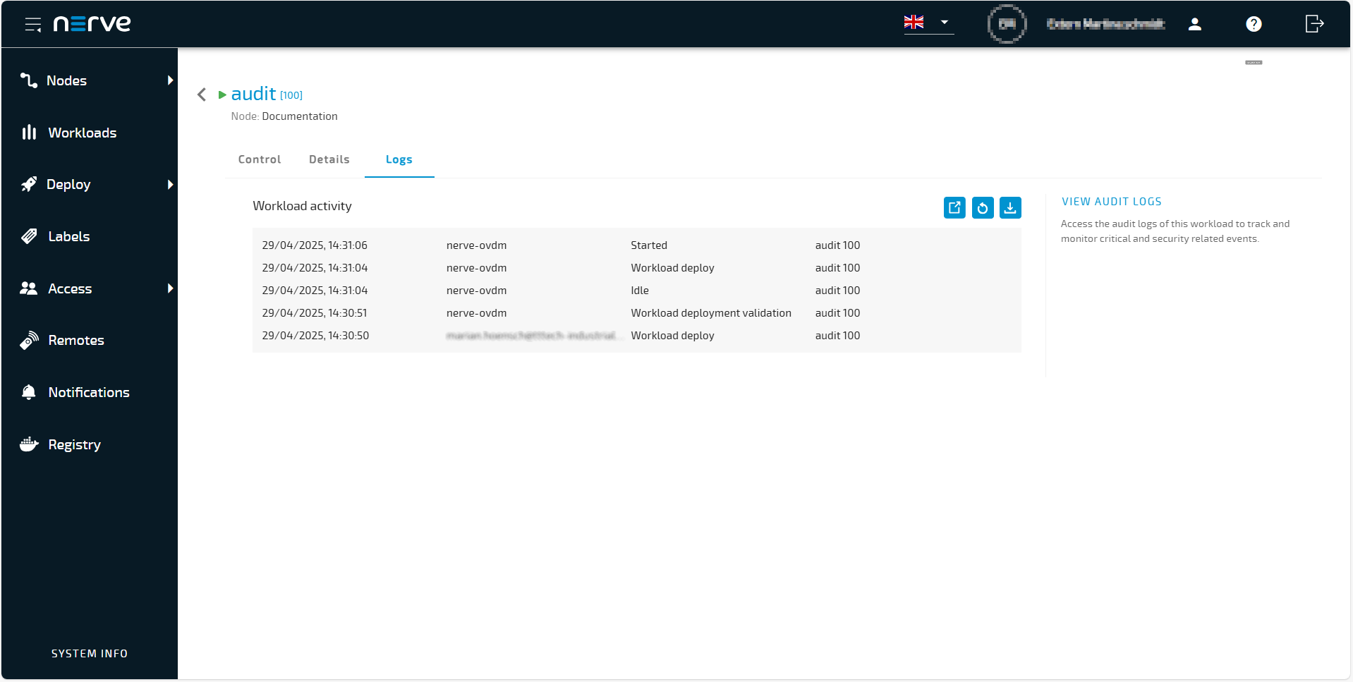 Select VIEW AUDIT LOGS, in the other section of the tab, to view the custom audit logs filtered for this workload in Open Search. You can define custom audit logs in a JSON file within your workload. Refer to the code block below for an example of how the JSON file must be structured.  Other tabs, such as the Details tab, will be available depending on the workload type. Refer to Workload type specifics for more information. |
| Control panel (5) | The following control options are available:
|
| Message window (6) | The message window displays the latest message the workload has sent out including a time stamp. The type of message that is displayed here depends on the workload. Messages for VMs and Docker containers:
Additional set of messages for VMs only:
Messages from CODESYS workloads:
|
| Usage statistics (7) | Virtual Machine workloads and Docker workloads have their assigned resources they can use. The use of these resources is displayed with bar graphs:
|
| Workload commands (8) | This area is reserved for different actions and features depending on the workload type. Which commands or elements appear depends on the workload type, permissions and whether the requirements for the command are met. As an example, for Docker workloads, the Apply configuration button only appears when a Docker volume has been defined. For Virtual Machine workloads, this space is occupied by resource allocation settings. Refer to Workload type specifics below for more information. |
| Remote Connections (9) | All configured remote connections to the workload are displayed here in a list. Remote connections to the workload can be established by selecting Connect in the list. Note that this area is empty if no remote connection has been defined. Refer to Remote Connections for more information. |


Note
Since CODESYS workloads can only be controlled through the Local UI, the workload control screen does not offer any control options. It offers a message window. the option to undeploy the workload and the remote connections list for establishing remote connections.
Custom audit log
Nerve offers a simple, certified audit logging solution that forwards logs to the Management System, allowing your Docker workload to utilize this feature without vendor lock-in. The developer of the Docker workload has full control over the content of the audit log entry. The fields of the audit log entry are predefined and mandatory:
- timestamp: DateTime when the audit log event ocurred.
- category: Category of the event, chosen by the developer (e.g., Configuration change).
- source: Source of the change (e.g., process name or user name).
- type: Type of action (e.g., Start/Stop, Restart).
- event_id: Chosen by the developer, can be a unique combination of source, category, type, and result.
- event_result: Result of the event (e.g., success, failure).
This field is optional and can include additional application-related information.
- message: Can include any custom or additional information relevant to the context of the application.
Nerve automatically adds the container name and the Serial Number of the node from which the log entry originated to the audit log entry.
You will use the existing log mechanism for your applications. To ensure a console log entry becomes an audit log entry and appears in the separate OpenSearch dashboard, two conditions must be met:
- The log must follow the predefined structure.
- Include a Nerve-defined keyword that precedes the audit log entry.
Refer to the Log Tab description of the Workload control for instructions on accessing the Audit logs in the Management System.
You can see an example on how to create audit logs in the chapter below.
Example of a custom audit log
Note
Ensure that the JSON file is properly formatted and includes all the required fields. This will guarantee that the logs can be correctly identified and processed as audit logs.
Note that it is important to address nerve-audit-log in your JSON file.
    let counter = 1;

    const logMessage = () =>
    {
    const timestampAL = new Date().toISOString();

    console.log(`Dummy log message - regular log message, not audit log -  ${counter}`);

    const auditMsg =
    { 'nerve-audit-log':
        {
            timestamp: timestampAL,
            category: 'WL control',
            source: 'user@mail.com',
            type: 'start',
            event_id: '236589',
            event_result: 'success',
            message: `Dummy log message for testing audit logs - JSON.stringify()- ${counter}`
        }
    };

    counter++;

    console.log(JSON.stringify(auditMsg));
    };

    // Log message every 5 seconds
    setInterval(logMessage, 5000);
Workload type specifics
The table above covers the general workload control screen. Find below exclusive control options per workload type. Note that the options below will not appear in the workload control screen unless the requirements are met.
CODESYS workloads
| Item | Description |
|---|---|
| Replace version | Select this to open an overlay displaying all available versions of this workload. Select a version from the list to deploy it to the node in a quick way. Refer to Replacing the version of a deployed workload for more information. |
Docker workloads
| Item | Description |
|---|---|
| Apply configuration | This element only appears if configuration storage was defined. Selecting this allows the upload of configuration files. The configuration files have to be archived and uploaded in a ZIP file. For more information, refer to Applying configuration files to a workload below. |
| Replace version | Select this to open an overlay displaying all available versions of this workload. Select a version from the list to deploy it to the node in a quick way. Refer to Replacing the version of a deployed workload for more information. |
| Details tab | The Details tab shows defined environment variables and mapped ports for Docker workloads. |
Docker Compose workloads
| Item | Description |
|---|---|
| Replace version | Select this to open an overlay displaying all available versions of this workload. Select a version from the list to deploy it to the node in a quick way. Refer to Replacing the version of a deployed workload for more information. |
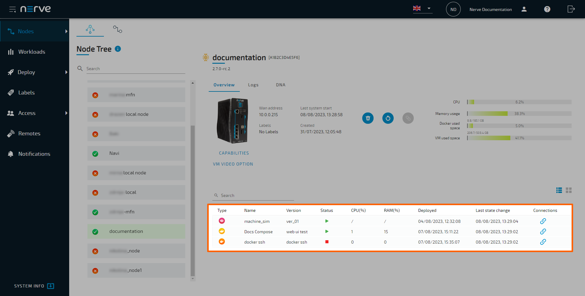
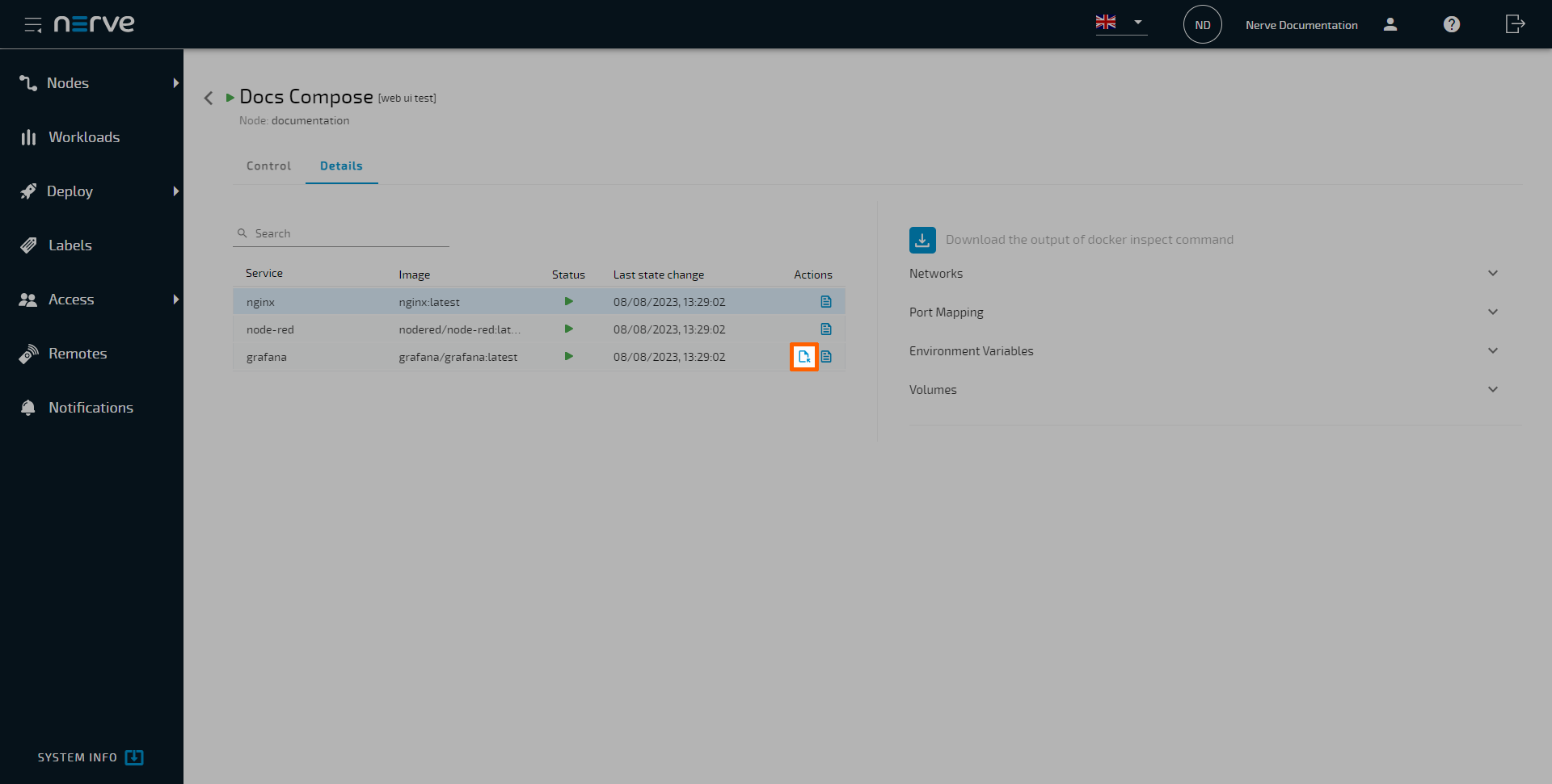
| Details tab | The Details tab for Docker compose workload shows the list of services that are part of the Docker Compose workload and a summary of the docker inspect of each service: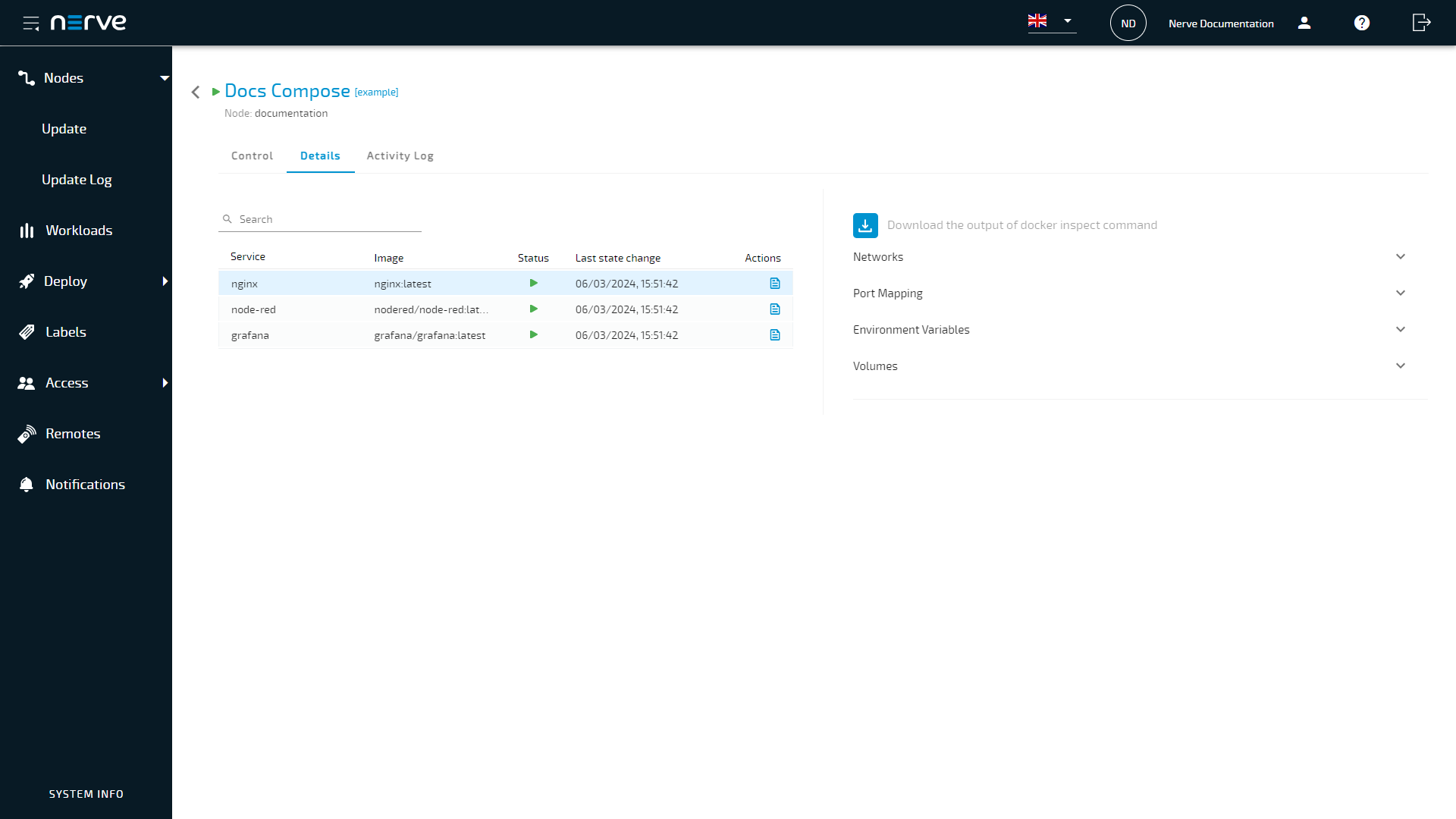 The left half shows the list of services with their names according to the compose file under Service and the image path of the container image under Image. Action columns show a maximum of two icons:
docker inspect command of the selected service. Select the downward arrows to expand the output of the command for Networks, Port Mapping, Environment Variables or Volumes. Select the download symbol above to export the entire output of the docker inspect command for the selected service. |
| Application web UI links | Visualizations or web UIs of applications that offer them can be accessed without the need of a remote connection. For this, ports need to be defined for each service in the range of 8500 — 8600 on the host. A link to the web UI is then generated by the Nerve system and available in the workload management section of the Local UI.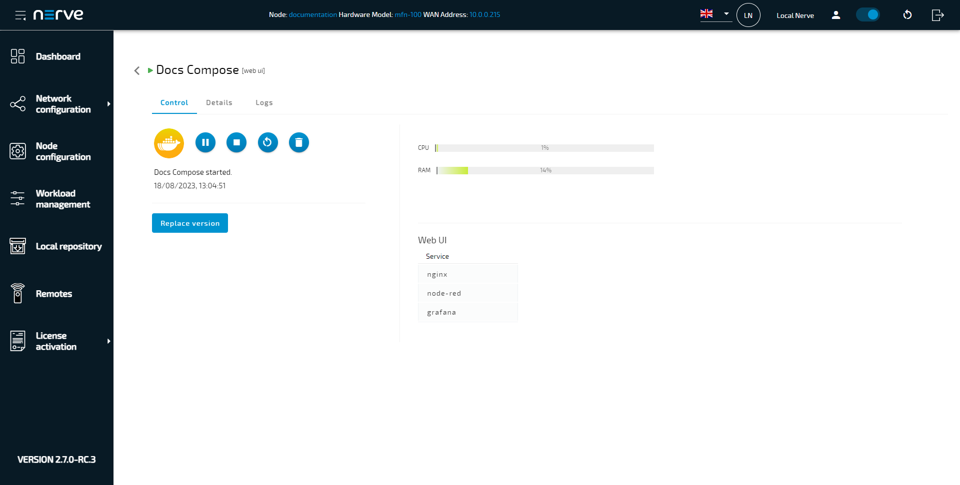 Refer to Docker Compose file for more information. |
Virtual Machine workloads
| Item | Description |
|---|---|
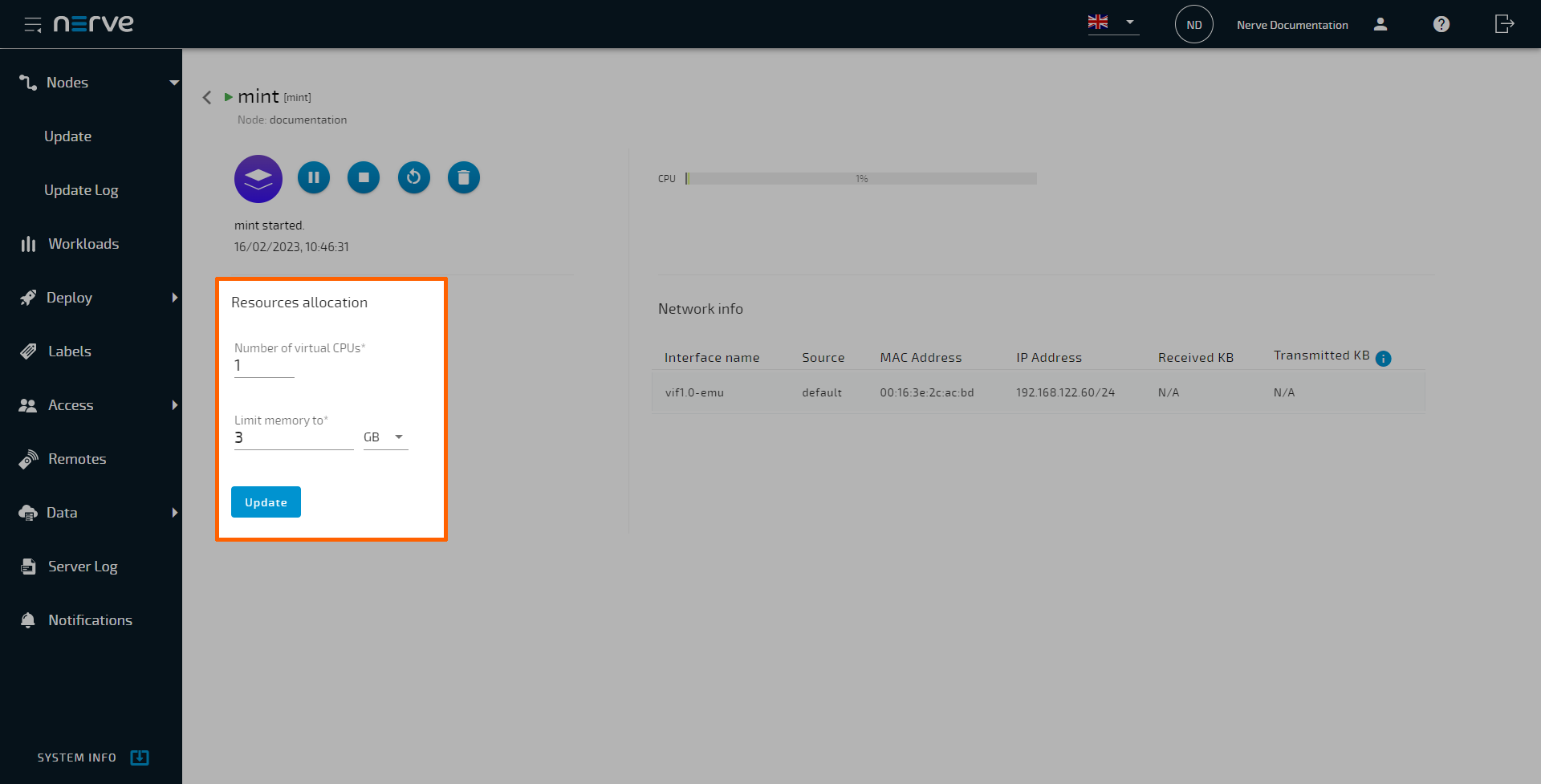
| Resources allocation | The allocation of resources for Virtual Machine workloads can be modified while the workload is deployed and running on a node. This allows for balancing of resources when several Virtual Machine workloads are running on one node. For more information, refer to Changing resource allocation of a deployed Virtual Machine workload below. |
| Network info | View information about networks attached to virtual machines in a read-only form. The information collected pertains the interface name, the source interface name on the Nerve host, the MAC address, the IP address, as well as the amount of received and transferred network data. Refer to Virtual machine network info below for more information. |
| Snapshot | The current configuration of a virtual machine running in the Nerve system can be temporarily saved by taking a snapshot. One snapshot can be created at a time, either manually or through scheduling an automatic snapshot. They are designed to be temporary save states or fallbacks before a virtual machine is configured or updated. The process takes seconds or minutes, and the result is a dynamically growing file stored on the Nerve Device. Note that snapshots are not persistent. If the workload is undeployed, the snapshot is lost. Refer to Virtual machine snapshots below for more information. |
| Backup | Saving a certain or optimal configuration of a virtual machine can be done with backups. Backups can only be created manually, and they take much longer to create compared to snapshots. They are not designed to be done frequently. Backups are stored in a separate repository that needs to be defined by the user in the Local UI. The repository needs to be an NFS server that is accessible for the Nerve system. The repository for virtual machine backups can be shared between nodes, making the deployment of a VM backup to another node possible. Note that an NFS server needs to be set up first and made accessible for the Nerve Device. Once the NFS server is set up, connect to the Local UI and define the NFS server as the VM backup repository. NFS v3 and v4 are supported. Refer to Virtual machine backups below for more information. |
Applying configuration files to a workload
Configuration files can be applied to deployed Docker workloads and singular services inside of Docker Compose workloads through the workload control screen. In this case, configuration files are files that the application in the workload needs to perform a specific task. The nature of these files is completely dependent on the application. Therefore, these configuration files need to be prepared by the workload creator beforehand. They also need to be archived as a ZIP file so that they can be applied to a workload using the Management System. Configuration files can be applied to the workload while it is running, stopped or suspended.
Also, note that the workload needs to be properly configured before it is deployed in order to apply a configuration. At least one Docker volume needs to be defined and designated as configuration storage. For more information, refer to Settings for Docker workloads and Settings for Docker Compose workloads.
Note
Note that this functionality is also available in the Local UI.
- Select Nodes in the navigation on the left.
- Select the node tree symbol.
- Select a node with a deployed Docker workload from the node tree.
-
Select the Docker workload in the node details view on the right.
-
Select Apply configuration.
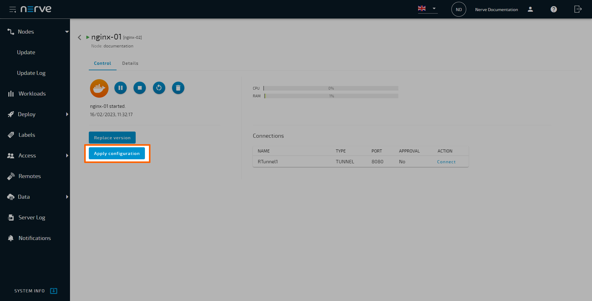
-
Select the plus icon to open the file browser.
- Select the ZIP file containing the configuration files.
-
Select Open to add the ZIP file.
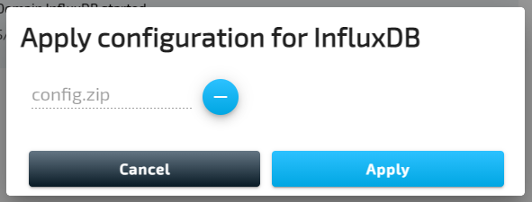
-
Select Apply.
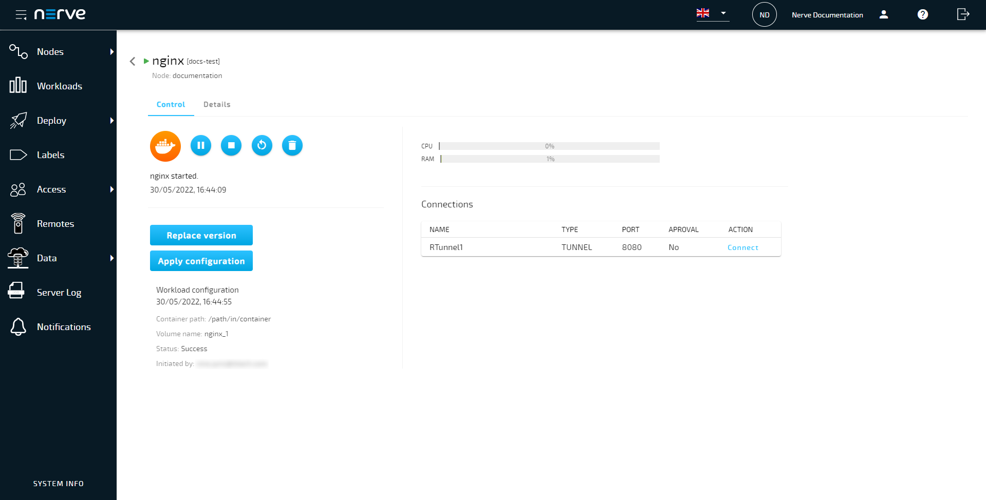
A success message will pop up in the upper-right corner once the ZIP file has been applied. Also, a new message window labelled Workload configuration is added. It includes the following information:
| Item | Description |
|---|---|
| Timestamp | A timestamp in the format M/DD/YYYY, h:mm:ss am/pm is added next to WORKLOAD CONFIGURATION in the header of the workload configuration message window. This indicates the most recent time configuration files have been applied. |
| Container path | This is the path of the Docker volume that has been defined in the workload version settings before the deployment of the workload. |
| Volume name | This is the name of the Docker volume that has been defined in the workload version settings before the deployment of the workload. |
| Status | This indicates whether the files containing in the ZIP file have been successfully transferred to the Docker container. |
| Initiated by | Here the user is listed that applied the configuration files. |
- Select Nodes in the navigation on the left.
- Select the node tree symbol.
- Select a node with a deployed Docker Compose workload from the node tree.
-
Select the Docker Compose workload in the node details view on the right.
-
Select the Details tab.
-
Select the Apply configuration icon from the Actions column.
-
Select the plus icon to open the file browser.
- Select the ZIP file containing the configuration files.
-
Select Open to add the ZIP file.
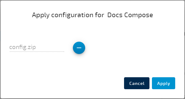
-
Select Apply.
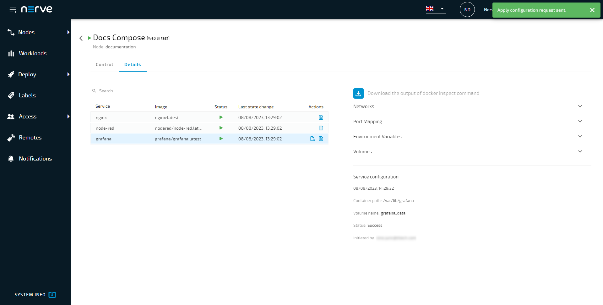
A success message will pop up in the upper-right corner once the ZIP file has been applied. Also, a new message window labelled Service configuration is added underneath the docker inspect summary on the right. It includes the following information:
| Item | Description |
|---|---|
| Timestamp | A timestamp in the format M/DD/YYYY, h:mm:ss am/pm is added underneath the Service configuration header of the message window. This indicates the most recent time configuration files have been applied. |
| Container path | This is the path of the Docker volume that has been defined in the workload version settings before the deployment of the workload. |
| Volume name | This is the name of the Docker volume that has been defined in the workload version settings before the deployment of the workload. |
| Status | This indicates whether the files containing in the ZIP file have been successfully transferred to the Docker container. |
| Initiated by | Here the user is listed that applied the configuration files. |
Changing resource allocation of a deployed Virtual Machine workload
The allocation of resources for Virtual Machine workloads can be modified while the workload is deployed and running on a node. This allows for balancing of resources when several Virtual Machine workloads are running on one node. Note that the workload automatically restarts in order to apply the changes.
- Select Nodes in the navigation on the left.
- Select the node tree symbol.
- Select a node with a deployed Virtual Machine workload from the node tree.
-
Select the Virtual Machine workload in the node details view on the right.
-
Edit the values of Number of virtual CPUs and Limit memory to to the desired values.
-
Select Update.
- Select Yes in the pop-up that appeared.
A green notification pops up in the upper-right and the Virtual Machine workload is automatically restarted to apply the changes.
Note
This functionality is also available in the Local UI. Log in to the Local UI and select Workload management in the navigation on the left. Select a Virtual Machine workload and follow the steps above.
Virtual machine network info
Information about networks attached to virtual machines can be looked into in read-only form. Refer to the Network info area in the workload control screen of a Virtual Machine workload to view the information. Here is how to reach the workload control screen in the Local UI and the Management System:
| Location | Path |
|---|---|
| Local UI | Workload management > Select the VM workload. |
| Management System | Nodes > Select a node from the node tree that has a compatible virtual machine deployed. > Select the VM workload. |
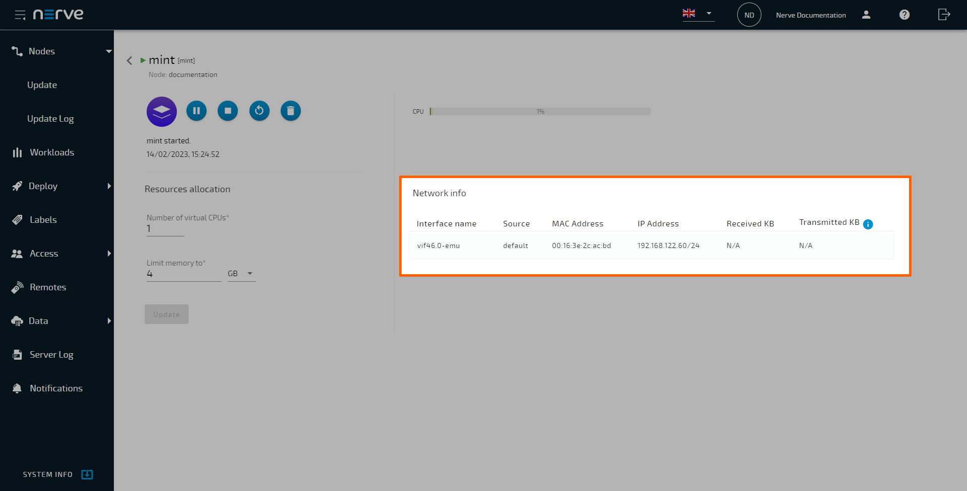
Here is an overview of the information shown.
| Item | Description |
|---|---|
| Interface name | Name of the virtual network device attached to the host interface. |
| Source | This is the name of the Nerve network interface that was assigned when provisioning the workload. However, the name displayed here is the name of the interface on the host. This means bridged interfaces (rtvm and isolated1-5) will be displayed differently, i.e. isolated1 will be displayed as br-isolated1 etc. |
| MAC Address | MAC address assigned to the virtual network device. |
| IP Address | This is the IP address of the interface, either given by a DHCP server or set manually. |
| Received KB | Network data received since last VM workload start. |
| Transmitted KB | Network data transferred since last VM workload start. |
If there are no networks attached to the workload, the dialog will be empty.
Virtual machine snapshots
The current state of a virtual machine running in the Nerve system can be temporarily saved by taking a snapshot. One snapshot can be created at a time, either manually or through scheduling an automatic snapshot. They are designed to be fallbacks before a virtual machine is updated or before its configuration is changed. The process takes seconds or minutes, and the result is a dynamically growing file stored on the Nerve Device. Note that snapshots are not persistent. If the workload is undeployed, the snapshot is lost.
Note
- Snapshots are supported only for VMs using the QCOW2 image format. Snapshots are not supported for virtual machines using IMG or RAW image files.
- Keep in mind that by reverting a snapshot all changes occurred in the VM after the creation of the snapshot will be lost.
Enabling virtual machine snapshots
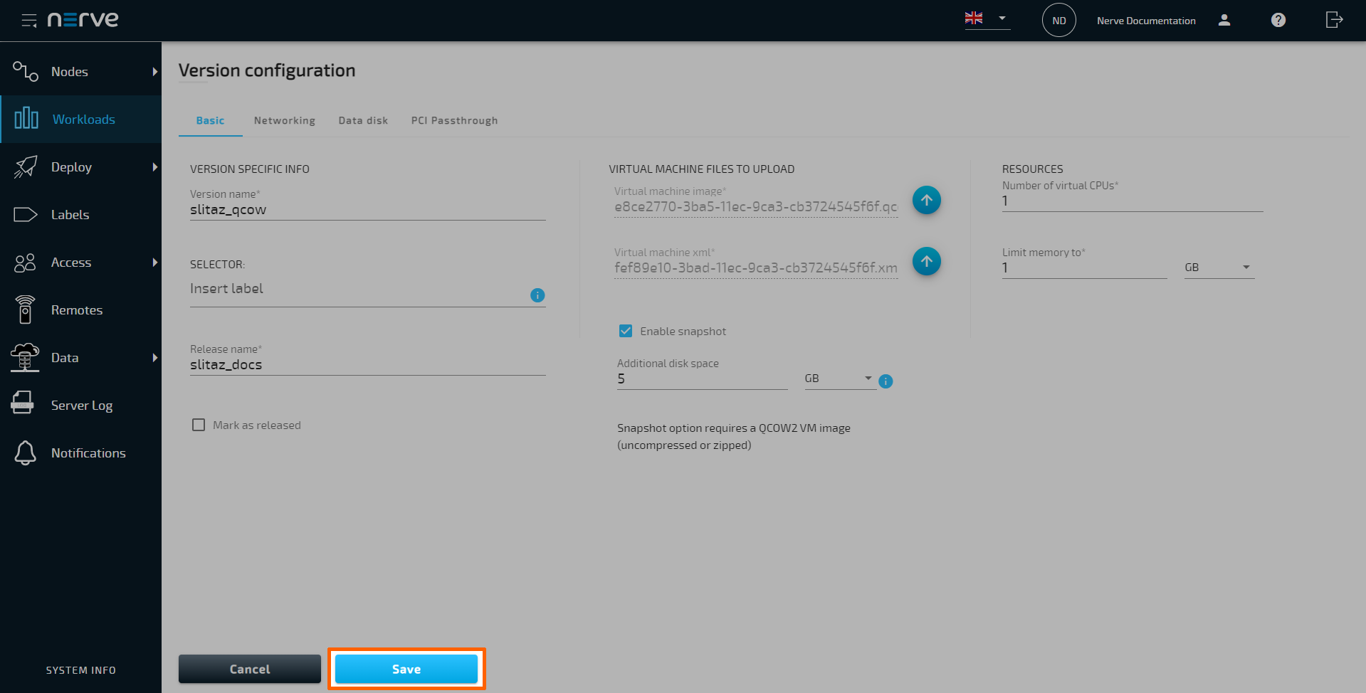
Snapshots are only available to virtual machine workloads using a QCOW2 image. So when following Provisioning a Virtual Machine workload, make sure to convert the resulting IMG file to QCOW2 and use the QCOW2 file when creating the workload in the Management System. For existing virtual machine workloads, convert the uploaded IMG or RAW file to QCOW2, replace it with the new QCOW2 and redeploy the VM workload. To enable snapshots in the Management System, follow the steps below:
Note
Snapshots cannot be taken for VM workloads that have an additional disk defined through the Management System.
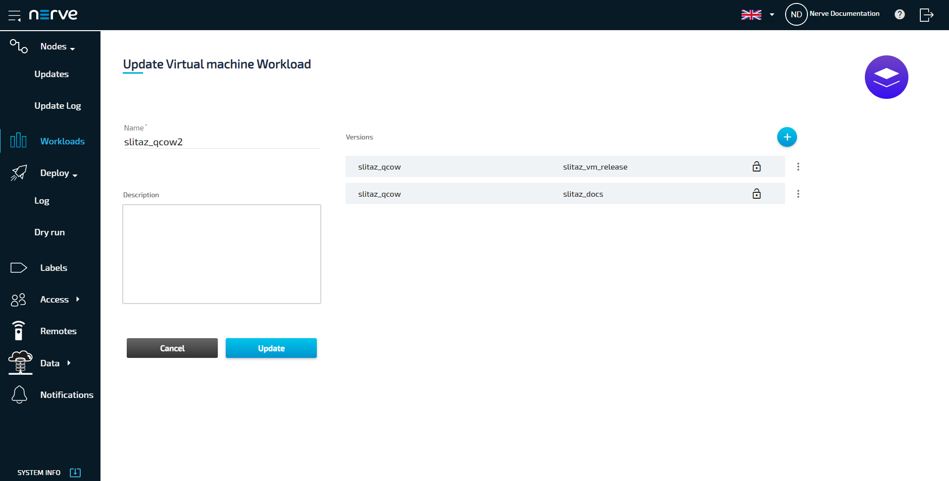
- Select Workloads in the navigation on the left.
- Select a Virtual Machine workload with a workload version that uses a QCOW2 image.
-
Select the appropriate workload version.
-
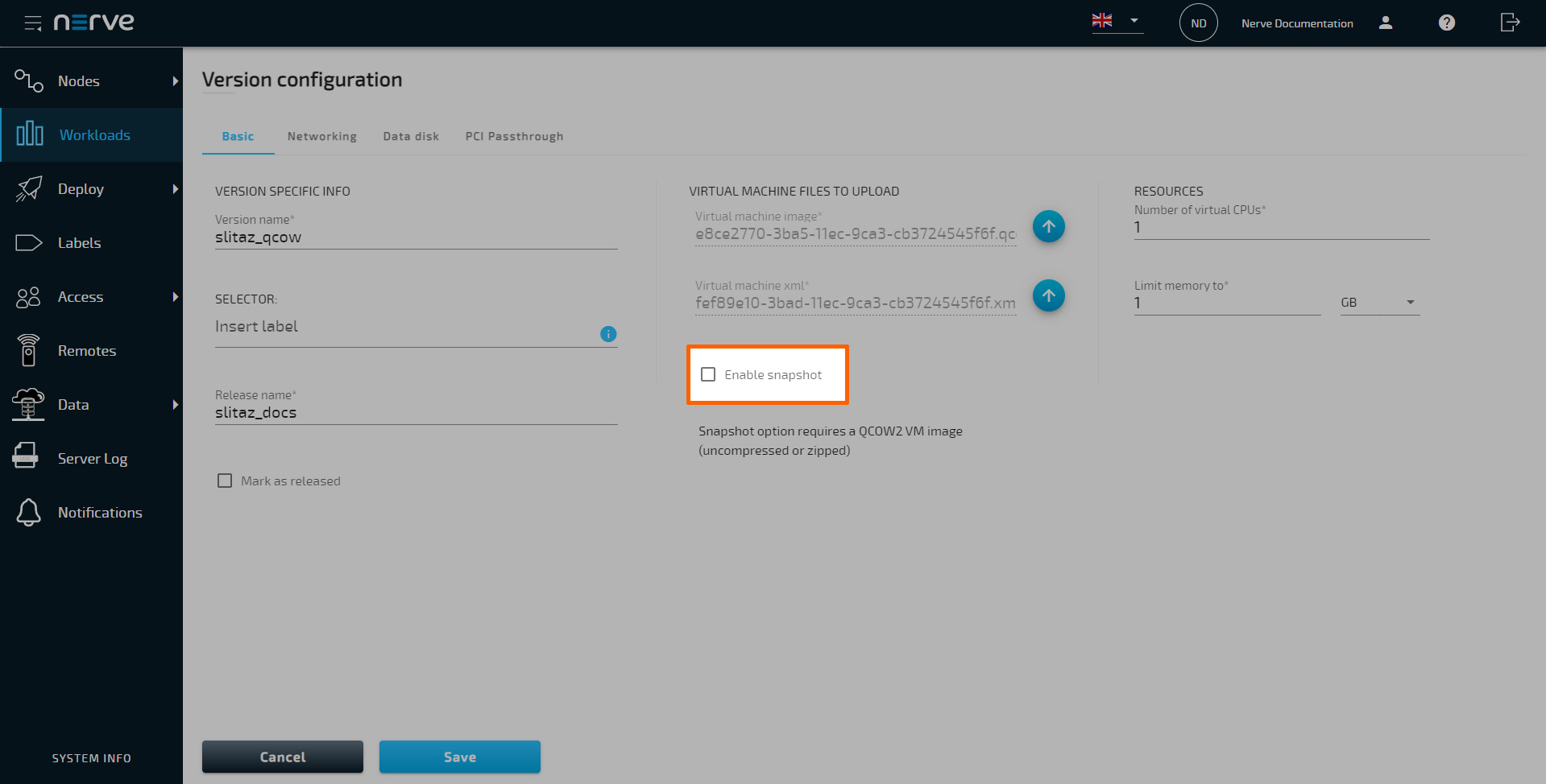
Tick the checkbox next to Enable Snapshot.
-
Enter a value under Additional disk space to define additional disk space for the snapshot. The additional disk space depends on the defined memory for the VM, the VM disk size and should also include about 3% of overhead.
Note
Keep in mind the duration of how long the snapshot will be kept. The longer a snapshot is kept, the larger it will grow, requiring a larger amount of additional disk space. As an example, keeping a snapshot for a month could possibly double its size.
-
Select Save to save the changes.
-
Follow Deploying a workload to deploy the workload.
With snapshots enabled, they can be taken manually or automatically through scheduling an automatic snapshot.
Taking a virtual machine snapshot manually
Taking a snapshot is done from the workload control screen in the Local UI and the Management System. To reach the workload control screen, follow the paths below:
| Location | Path |
|---|---|
| Local UI | Workload management > Select the VM workload. |
| Management System | Nodes > Select a node from the node tree that has a compatible virtual machine deployed. > Select the VM workload. |
The snapshot menu is accessed through the Snapshot tab. Snapshots can be taken in any state — running, stopped or suspended.
Note
If a VM is running a heavy process before taking a snapshot, it is recommended to stop the VM before taking the snapshot. Data could be lost. For scheduled snapshots, set VM state to Stopped.
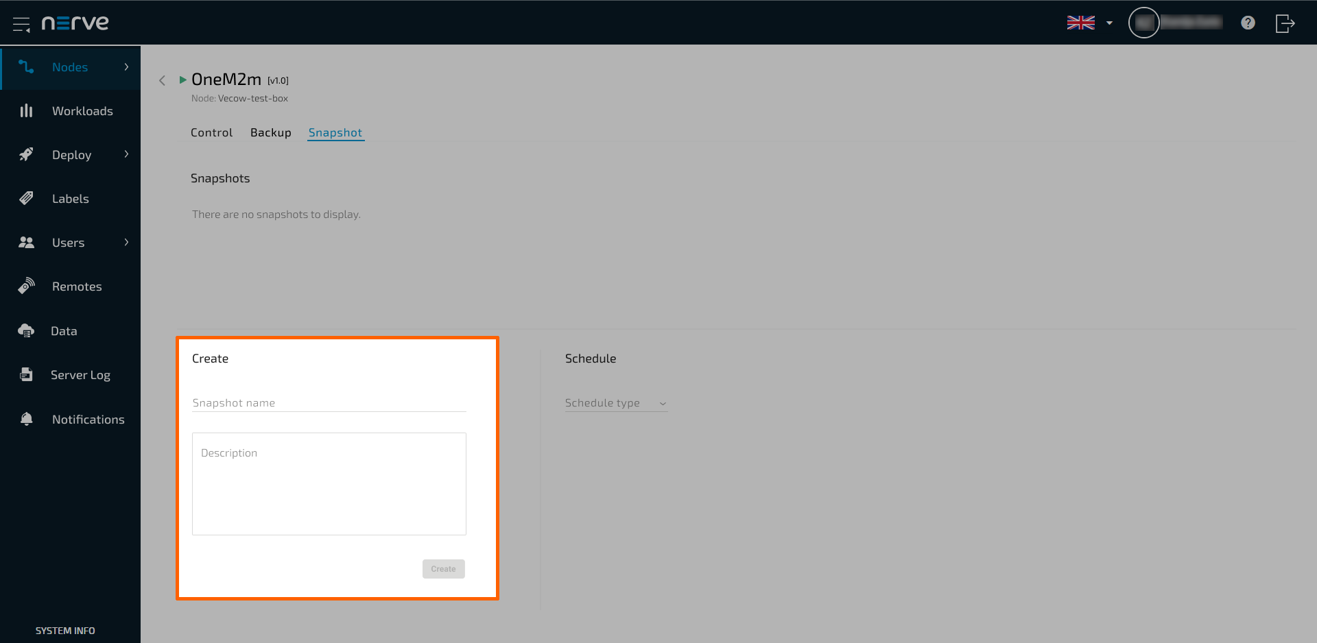
- Select the Snapshot tab to access the snapshot menu.
-
Enter a custom name and description to make the snapshot easier to identify.
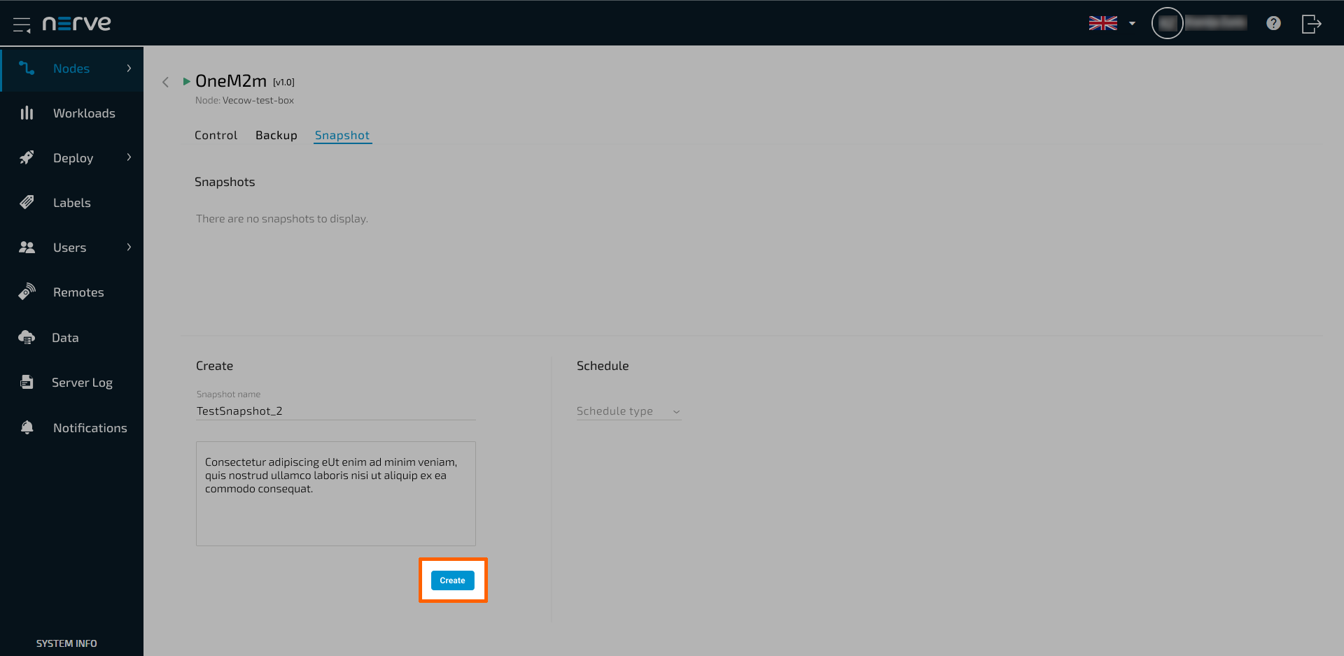
-
Select Create to create the snapshot.
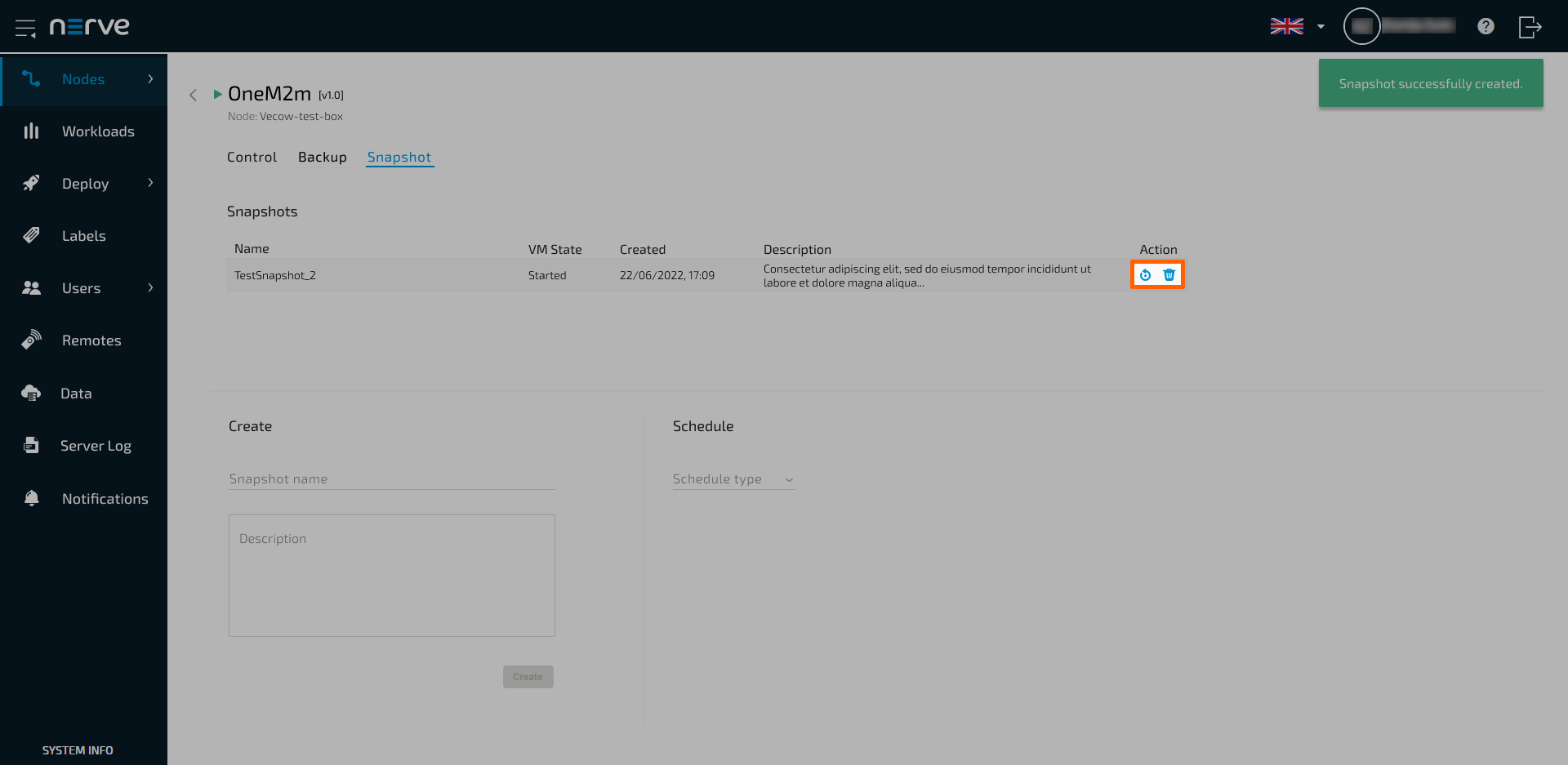
The snapshot now appears in the list. Revert to a snapshot by selecting the Restore symbol in the Action column. Delete a snapshot by selecting the Delete icon. Keep in mind that only one snapshot can be taken at a time.
Scheduling automatic snapshots
If taking snapshots is a recurring event or snapshots need to be taken in regular intervals, snapshots can be scheduled in the Local UI and the Management System. To reach the workload control screen, follow the paths below:
| Location | Path |
|---|---|
| Local UI | Workload management > Select the VM workload. |
| Management System | Nodes > Select a node from the node tree that has a compatible virtual machine deployed. > Select the VM workload. |
The Snapshot option is located on the left side underneath the workload icon. Note that scheduled snapshots always delete existing snapshots before creating a new one.
Note
If a VM is running a heavy process, it is recommended to set the VM state to Stopped. Data could be lost when the snapshot is taken. For scheduled snapshots, set VM state to Stopped.
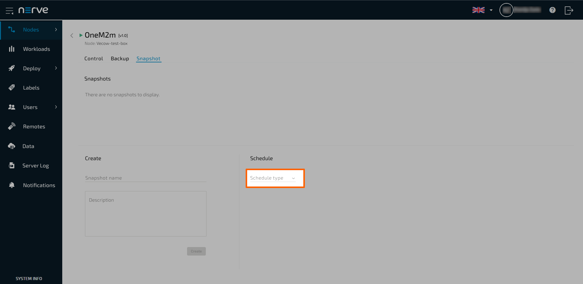
- Select the Snapshot tab to access the snapshot menu.
-
Select Interval or Day in the Schedule type drop-down menu under Schedule.
Note
In case of using an interval, note that the system does not keep memory of the already elapsed time. This means that after a node reboot, the interval timer is reset, and the interval starts over according to the configured interval.
-
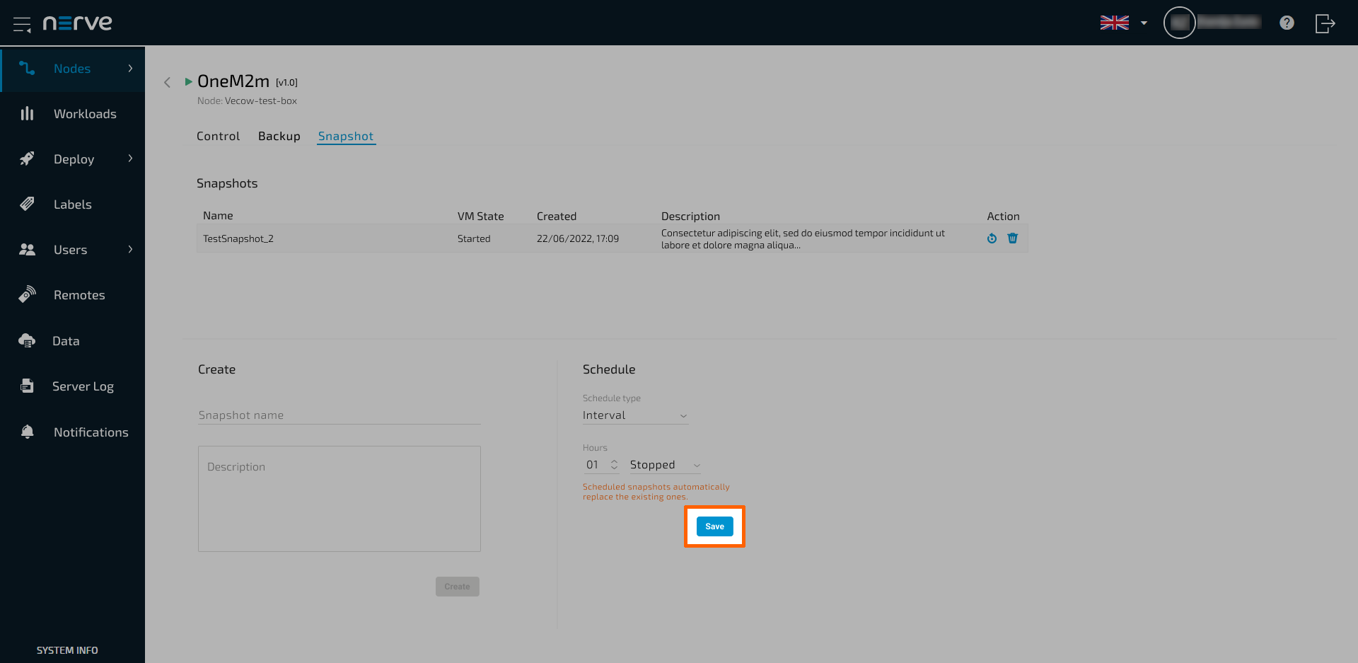
Fill in the values according to the selection:
Schedule Type Description Interval hh
Enter a numbered value. This is the interval in hours in between scheduled snapshots.
VM state- Current
The status of the VM will not be changed while the snapshot is being taken. - Stopped
The running VM is stopped, the snapshot is taken, and the VM is started again.
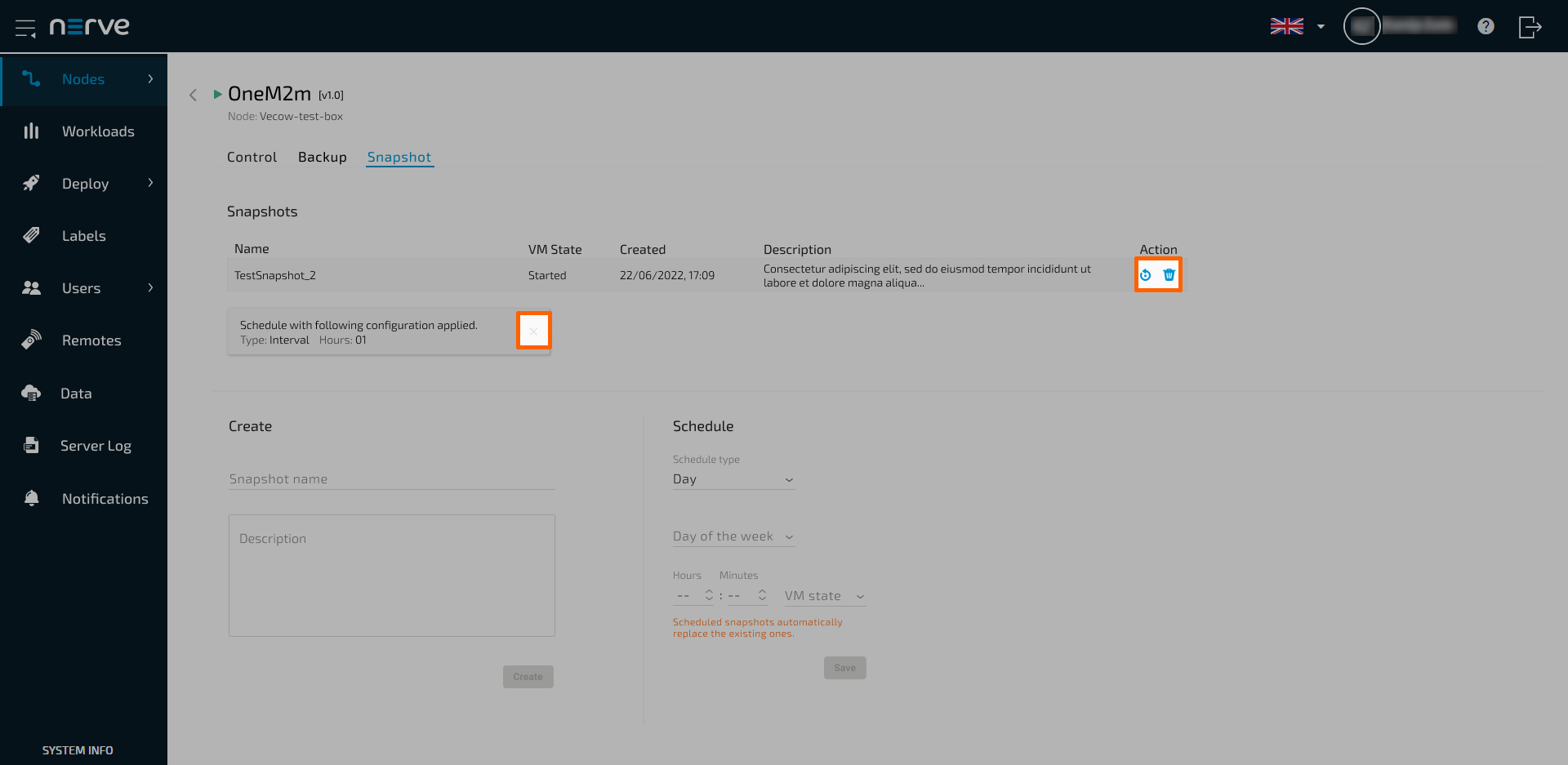
Day Day of the week
Select a day of the week or Every day.
Hours
Enter the hours of the time of day.
Minutes
Enter the minutes of the time of day.
VM state- Current
The status of the VM will not be changed while the snapshot is being taken. - Stopped
The running VM is stopped, the snapshot is taken, and the VM is started again.
- Current
-
Select Save.
Once the snapshot is taken at the scheduled time, it will appear in the list. Revert to a snapshot by selecting the Restore symbol in the Action column. Delete a snapshot by selecting the Delete icon. Disable the snapshot schedule by selecting the cross symbol of schedule notification window. Keep in mind that the next scheduled snapshot is going to delete the existing snapshot since only one snapshot can be taken at a time.
Virtual machine backups
Saving a certain or optimal configuration of a virtual machine can be done with backups. Backups can only be created manually, and they take much longer to create compared to snapshots. They are not designed to be done frequently. Backups are stored in a separate repository that needs to be defined by the user in the Local UI. The repository needs to be an NFS server that is accessible for the Nerve system. The repository for virtual machine backups can be shared between nodes, making the deployment of a VM backup to another node possible.
Note that an NFS server needs to be set up first and made accessible for the Nerve Device. Once the NFS server is set up, connect to the Local UI and define the NFS server as the VM backup repository. NFS v3 and v4 are supported.
-
Access the Local UI on the node. This is Nerve Device specific. Refer to the table below for device specific links to the Local UI. The initial login credentials to the Local UI can be found in the customer profile.
Nerve Device Physical port Local UI MFN 200 P3 http://172.20.2.1:3333 MFN 100 P1 http://172.20.2.1:3333 Kontron KBox A-250 ETH 2 <wanip>:3333
To figure out the IP address of the WAN interface, refer to Finding out the IP address of the device in the Kontron KBox A-250 chapter of the device guide.Siemens SIMATIC IPC427E X1 P1 http://172.20.2.1:3333 Siemens SIMATIC IPC BX-39A X1 P1 http://172.20.2.1:3333 Vecow SPC-5600-i5-8500 LAN 1 http://172.20.2.1:3333 Compulab fitlet3 LAN3 http://172.20.2.1:3333 -
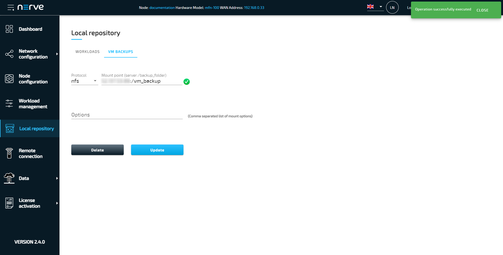
Select Local repository in the navigation on the left.
-
Select the VM BACKUPS tab.
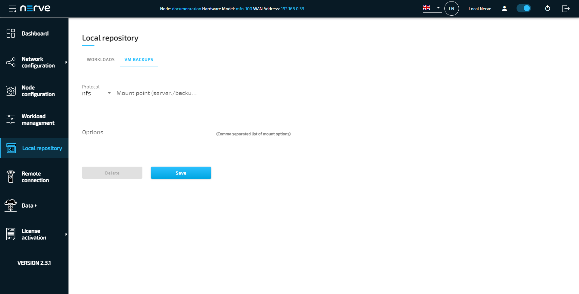
-
Enter the following information:
Field Value Protocol The only available protocol is nfs. Mount point (server:/backup_folder) Enter the URL of the NFS server in the format server:/backup_folderthat was set up before. The NFS server needs to be accessible for the Nerve system.Options Enter the list of mount options here. Mount options need to be separated by a comma. Refer to this link for NFS mounting options. Note that the following options are not considered by the system: - rw (read/write)
- ro (read only)
- fg (foreground)
- bg (background)
- O (Overlay mount)
- remount
-
Select Save.
A green check mark appears next to the server address when the connection is successful.
Creating a virtual machine backup
VM backups are taken in a stopped state. The Nerve system will stop the VM automatically if it is not stopped manually before. Note that an NFS server needs to be set up and defined as a VM backup repository before creating a backup. To reach the workload control screen, follow the paths below:
| Location | Path |
|---|---|
| Local UI | Workload management > Select the VM workload. |
| Management System | Nodes > Select a node from the node tree that has a virtual machine deployed. > Select the VM workload. |
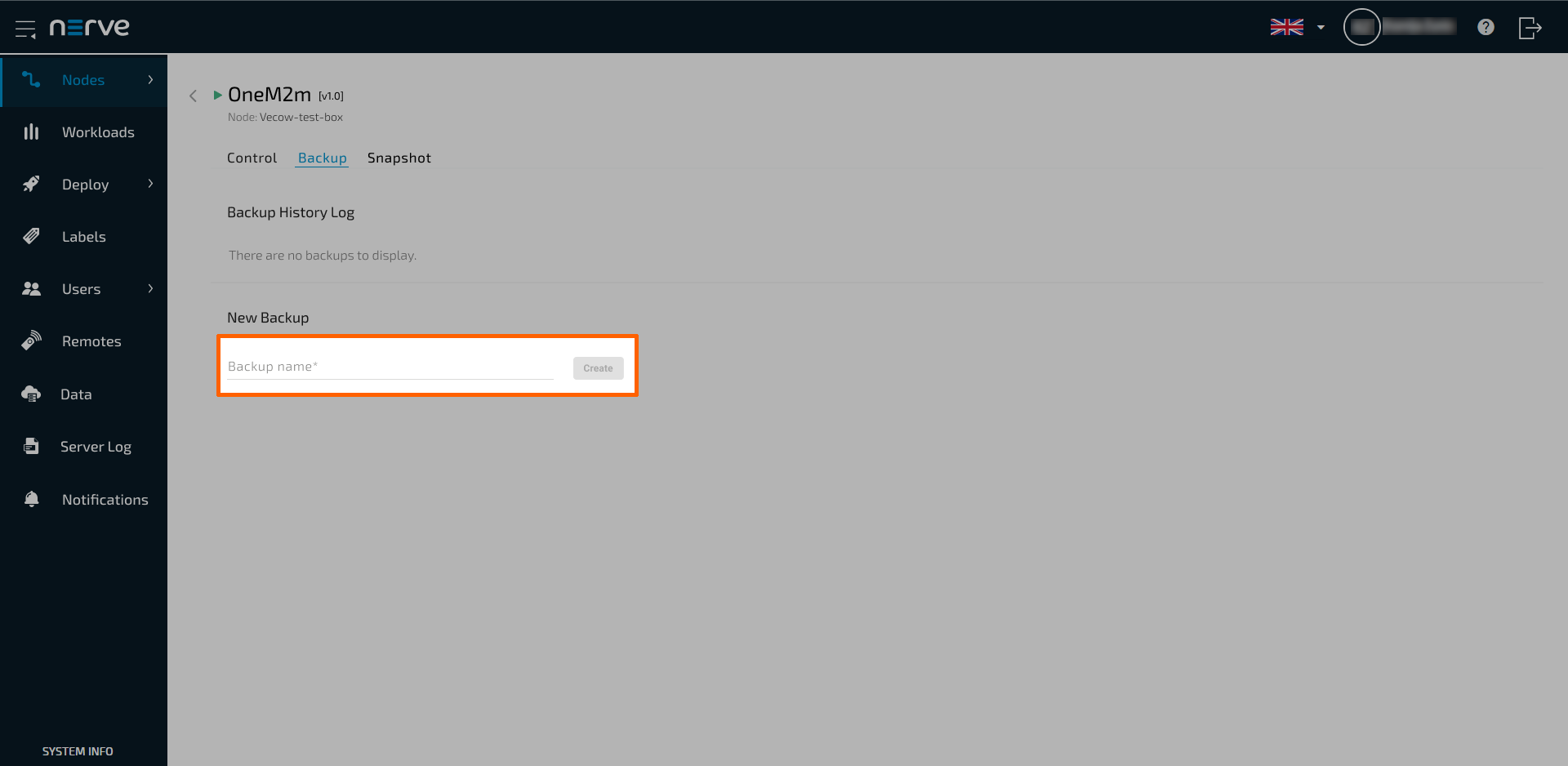
- Select the Backup tab to access the backup menu.
-
Enter a name in the Backup name field to make the backup easier to identify.
-
Select Create.
-
Select Yes.
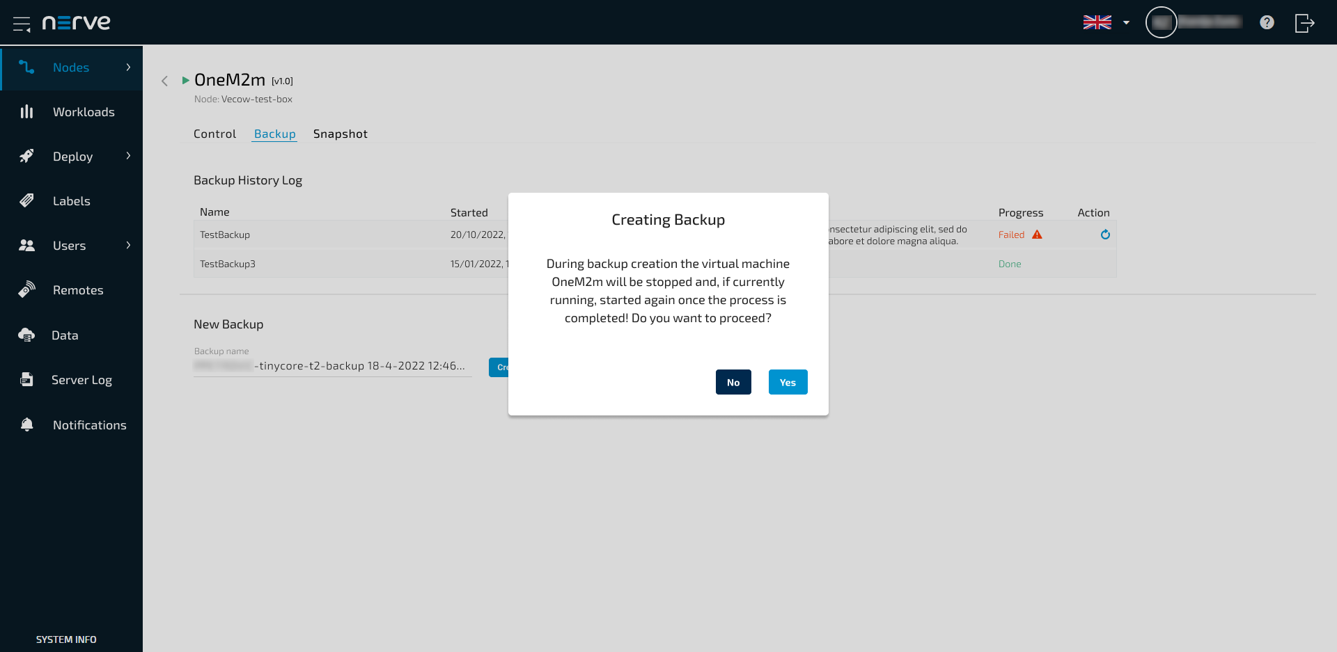
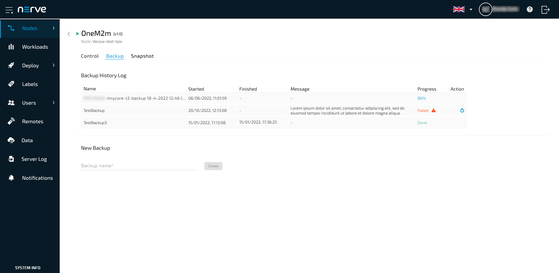
The backup creation process is now started. The duration of the backup creation depends on the size of the VM. It takes a considerable amount of time, as an identical copy of the VM is being created and transferred to the VM backups repository. A backup creation history is created and can be viewed in the UI.
Deleting a backup is done through connecting to the NFS server locally or remotely. Each VM backup consists of multiple files: image files, an XML and a JSON file. All files contained in the backup are listed in the JSON file containing the VM metadata.
Restoring a virtual machine backup
Backups can only be deployed in the Local UI. VM backups can be deployed at other nodes if they have the same VM backup repository set in the Local UI. Note that if an exact replica of a VM is desired, by keeping the original VM UUID and MAC address, the original VM needs to be undeployed first before deploying the backup.
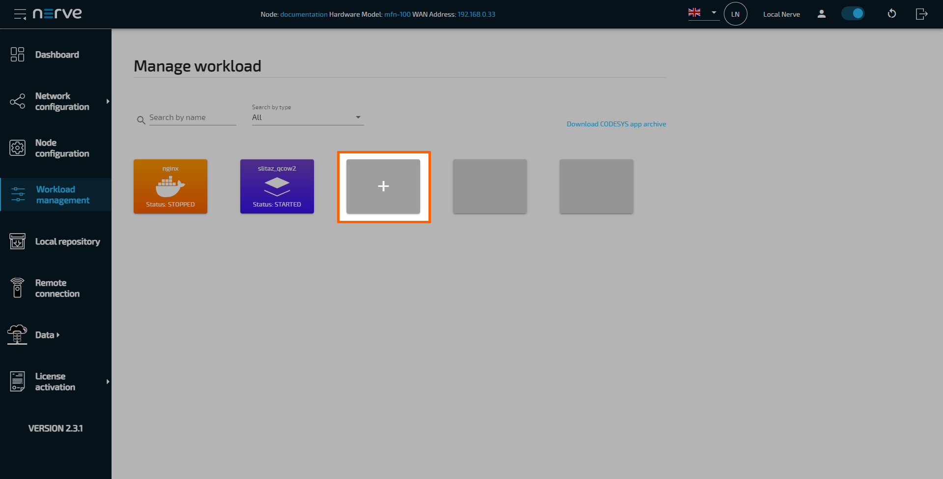
- Select Workload management in the navigation on the left.
-
Select the + tile to deploy a new workload.
-
Select the BACKUPS REPOSITORY tab.
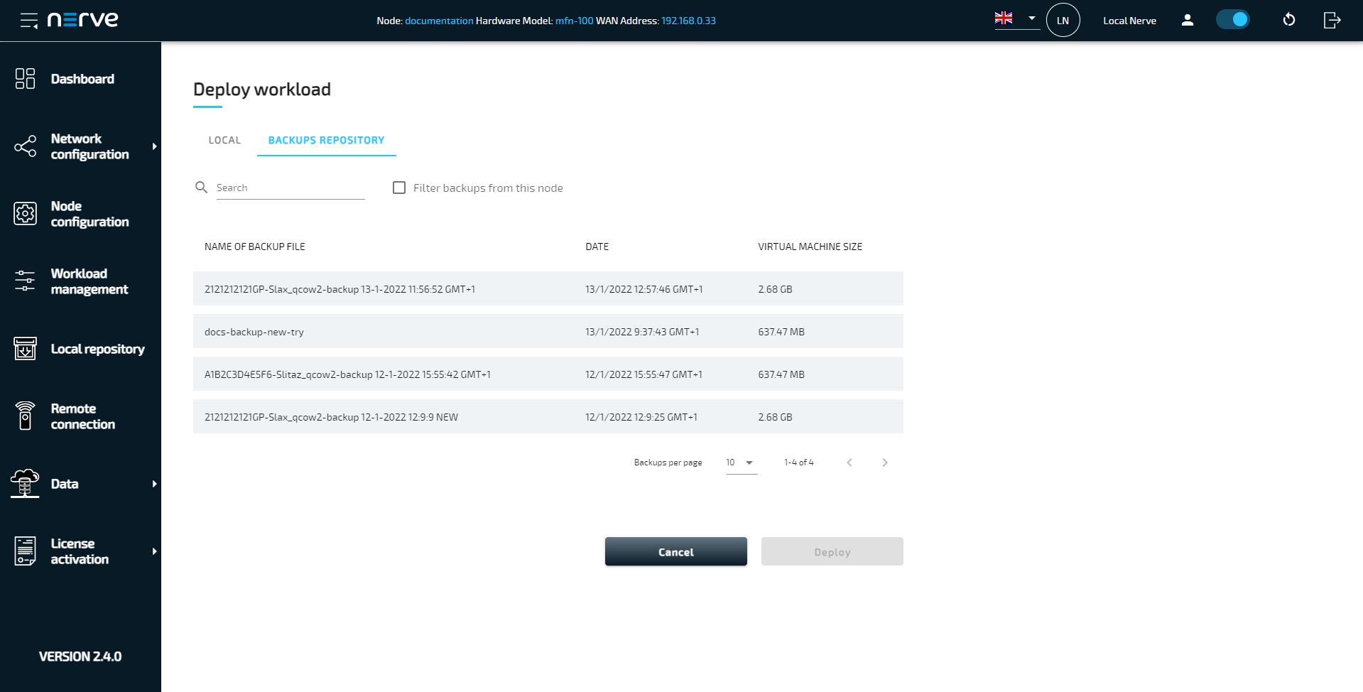
-
Select a backup from the list.
Optional: Tick the checkbox next to Filter backups from this node to show backups that were created on the current node.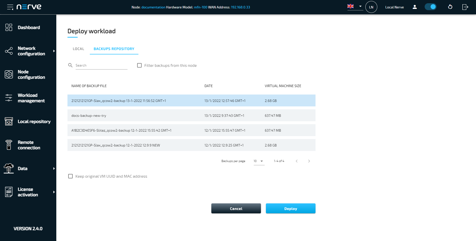
Note
When deploying a backup, the original VM UUID and MAC address can be preserved. Tick the checkbox next to Keep original VM UUID and MAC address to do so. In this case the original VM needs to be undeployed first, if it is still present on the node.
-
Select Deploy.
The VM backup will show up as a Virtual Machine workload in the workload management view once the deployment has finished.