Node internal networking
This chapter explains how a user can connect workloads (VMs and Docker containers) to services and network ports of a node. In order to do this, it explains the internal networking concepts in detail. Most workloads will need to be connected to a network, as networking is the main form of communication for workloads. They either want to connect to external servers or they are servers themselves, in which case they need to be made visible for their communication partners. The Nerve networking system enables both use cases.
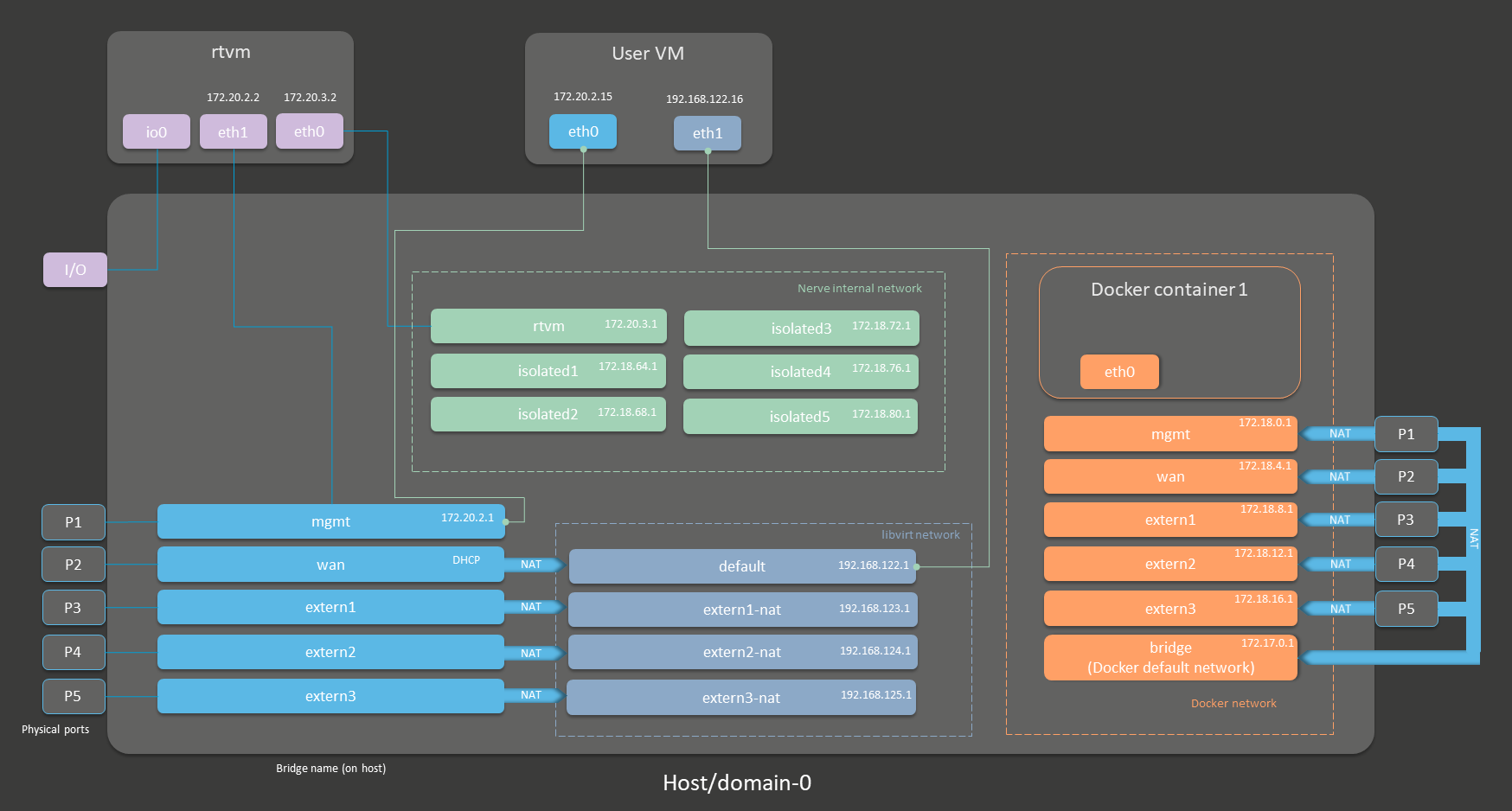
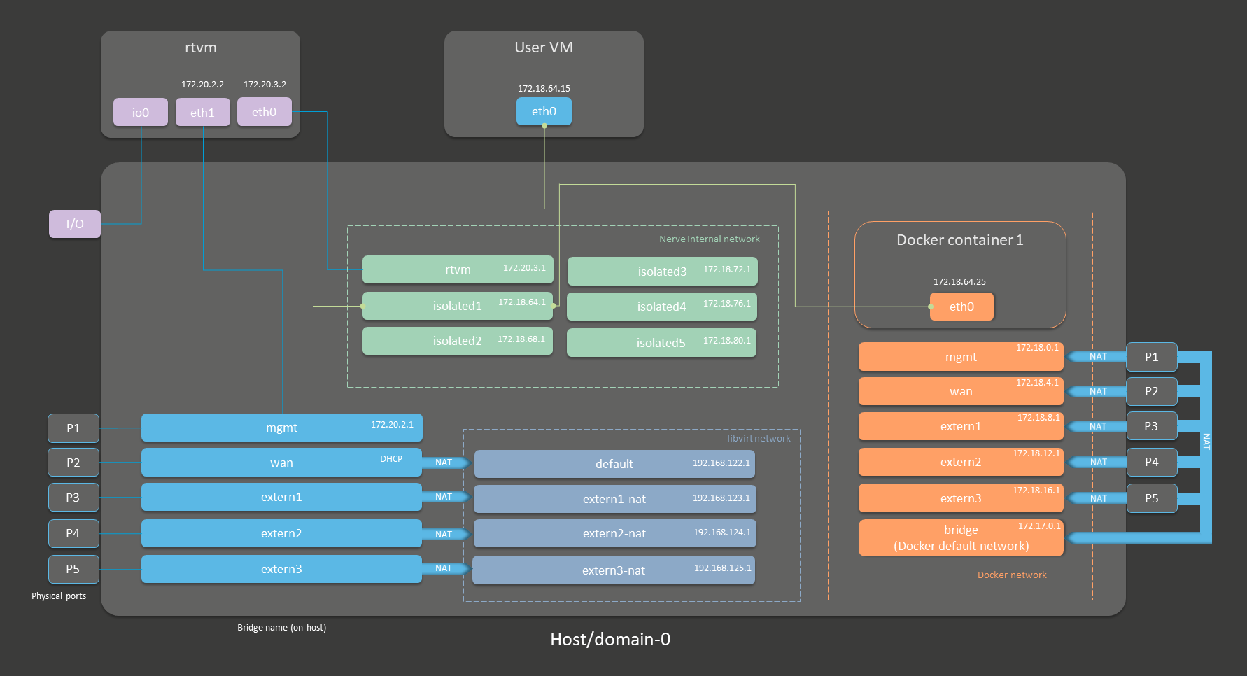
The image below shows an example node consisting of the host/domain-0. To further clarify the networking example it also has one Virtual Machine workload (User VM) and one Docker workload (Docker container 1) deployed. The virtual machine is depicted outside of the host and the Docker container is depicted in the Docker network inside of the host. For the sake of explanation, however, the workloads are not yet connected. This is done in the examples further below.
Note
The CODESYS runtime and the User VM in the depiction below are marked with an asterisk. This is due to there being two different installation types of Nerve:
- without a hypervisor
This variant contains the CODESYS runtime but cannot run VM workloads. - with the KVM hypervisor
This variant does not contain the CODESYS runtime but it can run VM workloads.
So depending on the installation type, there is either a CODESYS runtime available or VM workloads can be deployed but not both. In all illustrations further down below, both user VMs and the CODESYS runtime are included for informative purposes.

| Interface color | Description |
|---|---|
| Gray with blue frame | Physical network ports |
| Light blue | Linux network bridges displayed with their bridge names on the host |
| Dark blue | libvirt network interfaces for Virtual Machine workloads |
| Orange | Docker network bridges for Docker workloads |
| Green | Nerve internal network bridges shared between virtual machines, Docker containers and the host. They are not connected to any external, physical interface. |
| Purple | Interfaces related to the CODESYS runtime. |
The physical ports P1 to P5 and I/O of the Nerve Device (the MFN 100 in this case) are displayed on the left, touching the large dark rectangle that represents the host. The light blue interfaces connected to them inside the host are Linux bridged interfaces displayed with their names on the host. Highlighted by a dark blue dashed frame is the libvirt network with NAT interfaces. The system is set up so that the network bridges can be reached by connecting through the physical ports and that virtual machines can reach outside of the system through the NAT interfaces.
Highlighted by an orange dashed frame is the Docker network including the default Docker network (the orange interface labeled bridge), as well as Docker network equivalents of the Linux bridged interfaces. For the sake of easier representation, the physical ports P1 to P5 are duplicated to the right of the Docker network, again touching the host. This is done to show that Docker network interfaces can also be reached directly by connecting to the physical ports while also making sure to show that the libvirt network and the Docker network are separate from each other.
The Nerve internal network is highlighted by the green frame. It consists of the rtvm interface and the isolated interfaces. The isolated interfaces are designed for communication inside of the system, enabling communication between workloads. Using the isolated interfaces, communication can be established between Docker workloads, between Virtual Machine workloads, or between Docker and Virtual Machine workloads. The rtvm interface is designed for communication with the CODESYS runtime and can be used to enable communication of the CODESYS runtime with Docker workloads.
All interfaces colored in purple are related to the CODESYS runtime. Interfaces labeled eth are symbolic representations of interfaces that are used by virtual machines and Docker containers for communication with the Nerve system. The actual used interfaces depend on the Docker container or virtual machine.
Connections are displayed in three ways. Blue lines are connections that are predefined by the system. Blue arrows are used between bridged interfaces and the libvirt network to indicate NAT. Further down below, green lines are used as example connections that can be defined by the user.
As mentioned above, the image above represents the MFN 100. Refer to the device guide for information on the Nerve Device as the physical ports and the connection to their respective interfaces differ.
See the tables below for more information on the interfaces, their usage and their IP ranges. The table is structured by workload type and shows which interface can be used for each workload type.
Networks for Virtual Machine workloads
| Category | Descriptions |
|---|---|
| Bridged Interfaces | To connect to any of the bridged interfaces below, select Bridged from the drop-down menu and enter the name of the interface when provisioning a Virtual Machine workload.
|
| NAT Interfaces | To connect to any of the NAT interfaces below, select NAT from the drop-down menu and enter the name of the interface when provisioning a Virtual Machine workload. If a deployed virtual machine uses one of the predefined NAT interfaces, the IP address of the respective interface is assigned by a DHCP server with a subnet mask of 255.255.255.0. The DHCP pool contains the lower half of the respective address space, e.g. 192.168.122.2 to 192.168.122.128. The only exception is the default network.
|
| Nerve internal network | To connect to any of the interfaces in the Nerve internal network below, select Bridged from the drop-down menu and enter the name of the interface when provisioning a Virtual Machine workload. Isolated interfaces Isolated interfaces can be used to allow Virtual Machine workloads to communicate with Docker workloads and other Virtual Machine workloads. These networks cannot communicate outside of the system. The IP addresses of these interfaces are assigned by DHCP servers in the following ranges:
br-isolated1.rtvm Use this interface for communication with the CODESYS runtime and to establish connections between Virtual Machine workloads and the CODESYS runtime. The IP addresses are assigned in the range from 172.20.3.3 to 172.20.3.254. 172.20.3.2 is reserved for eth0 in the CODESYS runtime. |
Networks for Docker and Docker Compose workloads
| Category | Descriptions |
|---|---|
| Docker network | Since interfaces in the Docker network are behind NAT by the default, there is no drop-down menu to select Bridged or NAT when provisioning a Docker workload. Enter the network name of one of the networks below to connect a Docker workload to an interface.
|
| Nerve internal network | Since there is no drop-down menu to select Bridged or NAT when provisioning a Docker workload, enter the network name of one of the networks below to connect a Docker workload to an interface. Isolated interfaces Isolated interfaces can be used to allow Docker workloads to communicate with Virtual Machine workloads and other Docker workloads. These networks cannot communicate outside of the system. The IP addresses of these interfaces are assigned by DHCP servers in the following ranges:
Use this interface for communication with the CODESYS runtime and to establish connections between Docker workloads and the CODESYS runtime. The IP addresses are assigned in the range from 172.20.3.3 to 172.20.3.254. 172.20.3.2 is reserved for eth0 in the CODESYS runtime. |
The IP range of these internal docker networks can be changed during installation time.
- mgmt
- wan
- extern1-3
- isolated1-5
Please contact the Nerve Support for details and assistance.
Physical ports, other interfaces and connections
| Category | Descriptions |
|---|---|
| Physical ports | The physical ports are device dependent. They are included here for clarification of the image above. The MFN 100 is used as an example. Refer to the device guide for information on the specific hardware model of the Nerve Device.
|
| Other interfaces | eth These interfaces are symbolic representations of interfaces that are used by virtual machines and Docker containers for communication with the Nerve system. The actual interfaces used depend on the Docker container or virtual machine. The only exceptions are eth0 and eth1 for the CODESYS runtime as they are always defined with these names. io0 This interface is defined for communication between the I/O port and the CODESYS runtime. |
| Connections | Blue lines Blue lines signify connections that are predefined by the Nerve system. Green lines Green lines are example connections that could be defined by a user to connect virtual machines or Docker containers to the network. Blue arrows Blue arrows indicate a NAT between bridged interfaces and the libvirt network. |
The following sections are conceptual explanations. Workloads are attached to internal networks during the provisioning process. Refer to the provisioning chapters (Virtual Machine workloads and Docker workloads) in the user guide on how to provision workloads.
Addressing workloads by DNS name
Docker containers and virtual machines can be addressed by their DNS name, without the need of knowing the exact IP address. The DNS name of a Docker container and a virtual machine consists of the hostname or container name and the name of the network they are attached to. This behavior is explained further within the examples below, highlighting the DNS name that can be used where applicable.
Addressing a Docker workload by DNS name
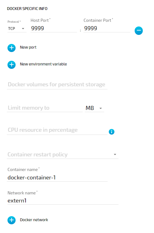
The DNS name of a Docker workload is defined in the provisioning process of the workload. Following the Provisioning a Docker workload chapter, the DNS name is determined by the Container name and Network name settings formatted as <containername>.<networkname>. As an example, the following screenshot shows these settings of a Docker workload:
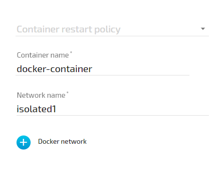
According to these settings, this Docker container can be reached under docker-container.isolated1 after being deployed to a node.
Addressing a Virtual Machine workload by DNS name
For Virtual Machine workloads the same principle applies, but the hostname part of the DNS name does not come from the workload provisioning settings in the Management System. The hostname is defined within the virtual machine, usually at creation time. As an example, if a Windows VM is generated on a Nerve Device, the hostname that is defined during the installation process of the Windows OS is required for addressing the Virtual machine per DNS name, e.g. DOCUMENTATION-PC.
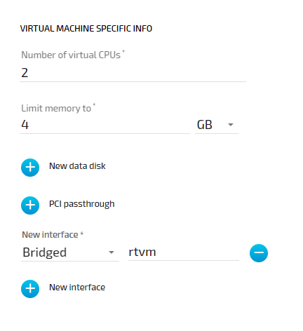
The network name is determined in the Management System by the New interface setting. As an example, the following shows this setting of a Virtual Machine workload:
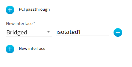
According to the machine name or hostname setting of the virtual machine and the network setting in the Management System, this virtual machine can be reached under DOCUMENTATION-PC.isolated1
Attaching virtual machines to a network
Virtual machine networking is comparable to installing a network card in the virtual machine and attaching it to the network with the network name given in the network drawing. For this example, there are two "network cards" installed in a user deployed virtual machine. They are located in the User VM and are labeled eth0 and eth1 in this example. Green lines indicate a user established connection.
There are two connections established here:
-
eth0 of the User VM is connected to the mgmt bridged interface so that the virtual machine can be reached through physical port P1. If the User VM has an SSH server set up, a service technician could gain access through P1 of the MFN 100.
-
eth1 of the User VM is connected to the default NAT interface for an internet connection protected by NAT on P2 of the Nerve Device.
Both interfaces have IP addresses in the designated ranges. 172.20.2.15 for eth0 was manually configured in the virtual machine and 192.168.122.16 for eth1 was assigned by the DHCP server.
Settings example
To achieve the functionality above, configure the interfaces of the Virtual Machine workload the following way during the provisioning process in the Management System:
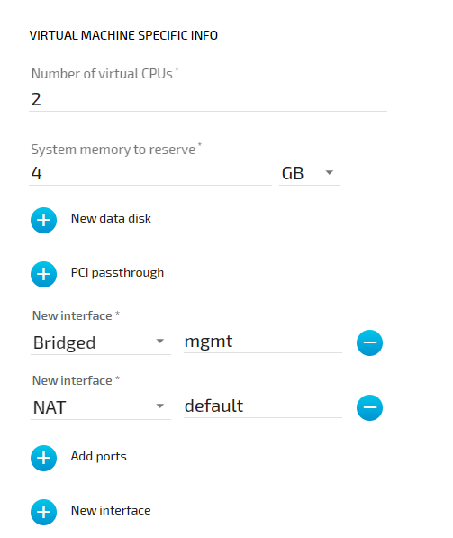
Settings example
To achieve the functionality above, configure the interfaces of the Virtual Machine workload the following way during the provisioning process in the Management System:
Communication of a Docker container with external devices
Docker containers can be attached to the Docker default network or respective Docker network interfaces to access other parts of the system or to communicate outside of the system. The Docker default network is called bridge and has the IP address 172.17.0.1 assigned. This interface is available on all physical ports (here P1 to P5). Therefore, when a Docker is connected to the Docker default network, the forwarded ports, as defined during workload provisioning in the port mapping section, are exposed on all physical interfaces.
For this example, the Docker container will be connected to the extern1 interface. In order to make a Docker port accessible from outside, specify the port and protocol during workload provisioning in the port mapping section. The chosen network, here extern1, defines on which physical port the exported Docker port can be accessed. The Docker container is connected to the extern1 interface in the Docker network, which makes the exported port available at physical port P3 to external devices.

The Docker container can be reached from the outside by connecting to the specified, exported port on the IP address of the P3 interface from an IP address in the range from 172.18.8.2 to 172.18.8.254.
Settings example
To achieve the functionality above, configure the Docker network name the following way during the provisioning process in the Management System. The Container name and the port mapping settings are placeholders chosen for this example:
Communication of a Docker container and a virtual machine through isolated networks
Nerve offers isolated network interfaces in the Nerve internal network for communication of workloads inside of the system. They can be used to establish communication between Docker containers, between virtual machines, or as in this example, between a Docker container and a virtual machine. Note that these interfaces do not communicate outside of the system.
The virtual machine has a "network card" installed. User VM 1 is connected to the isolated1 interface through eth0. Docker container 1 is connected through its interface eth0 to the same network interface, isolated1. Each interface has been assigned an IP address by a DHCP server in the designated range: 172.18.64.15 for eth0 of User VM1 and 172.18.64.25 for eth0 of Docker container 1.
Settings example
To achieve the functionality above, configure the interfaces of the Virtual Machine workload and the Docker workload the following way during the provisioning process in the Management System:
-
Virtual machine
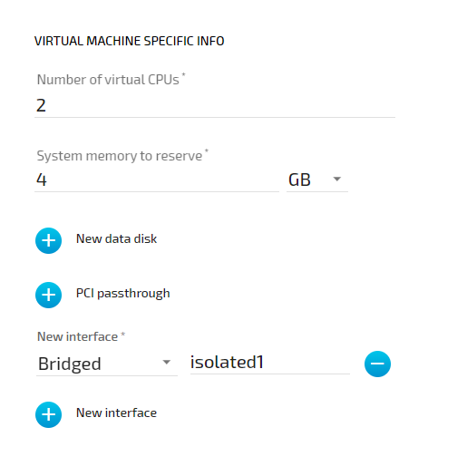
Assuming that the virtual machine is running Windows with the hostname DOCUMENTATION-PC which was defined in the creation process, the virtual machine can be reached under DOCUMENTATION-PC.isolated1.
-
Docker container

The Docker container can be reached under docker-container-1.isolated1 due to the Container name and the isolated network chosen in the Docker workload settings.
List of reserved TCP/UDP ports
In general, Nerve reserves the port range 47200 — 47399 on both TCP and UDP for internal usage. The following list states ports that are reserved.
| Port | Interface | Protocol | Reserved for |
|---|---|---|---|
| 22 | none | TCP | SSH daemon |
| 3000 | 172.20.2.1 | TCP | Previous location of Local UI |
| 3333 | 172.20.2.1 | TCP | Local UI |
| 47200 | 127.0.0.1 | TCP/UDP | System Log |
| 47201 | 127.0.0.1 | UDP | FluentBit |
| 47300 | 127.0.0.1 | TCP | Local MQTT broker |
| 47301 | 127.0.0.1 | TCP | Local MQTT broker |